What Is Draft Angle? Why Check Draft Before Mold Design?
What Is Draft Angle? A draft angle is a deliberate taper applied to a part surface to facilitate removal from a mold along a specified pull direction. In injection molding, appropriate draft can reduce friction between the molded part and the tooling, helping limit scuffing, deformation and ejection difficulties.
Draft should be evaluated before detailed mold design because a geometrically correct CAD model is not necessarily ready for injection molding. Insufficient draft may require product modifications, a different mold-opening direction or additional tooling mechanisms.
With PTC Creo Parametric, engineers can evaluate surface orientation through Draft Analysis and identify areas that require attention before developing core, cavity and moldbase geometry.
 What Is Draft Angle in Injection Molding?
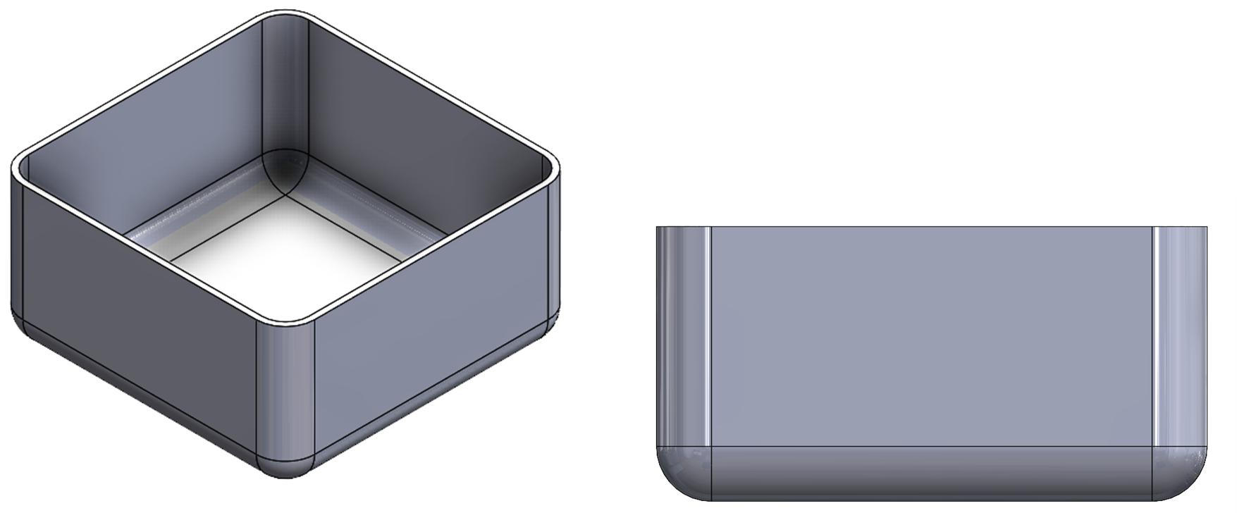 Draft angle describes the taper of a molded surface relative to the intended direction of part removal. On the vertical walls of plastic housings, the taper allows the surface to separate progressively from the mold as the part is ejected.
For example, a plastic enclosure with perfectly straight walls may remain in contact with the tooling over a substantial area during ejection. Introducing an appropriate taper can make release easier. The required angle depends on material, wall depth, surface finish, texture, shrinkage and tooling conditions.
Draft Angle vs Pull Direction
Draft Angle and Pull Direction are related but different. Draft Angle describes the taper of a surface, while Pull Direction defines the direction used to evaluate removal from the mold.
| Factor | Draft Angle | Pull Direction |
|---|---|---|
| Definition | Surface taper | Intended removal direction |
| Representation | Degrees | Direction vector or geometric reference |
| Purpose | Facilitates mold release | Defines the analysis direction |
| In Creo | Evaluated through Draft Analysis | Defined using a suitable reference |
Changing the Pull Direction can change the draft analysis results even when the product geometry remains unchanged. Selecting the intended mold-opening direction is therefore a critical preliminary step.
7 Reasons to Check Draft Before Mold Design
1. Identify Difficult-to-Release Surfaces
Surfaces with insufficient draft can increase contact and friction during ejection. Early analysis helps engineers identify potential release problems before detailed tooling is developed.
2. Reduce the Risk of Surface Damage
Inadequate draft may contribute to scuffing, drag marks or deformation when a molded part is removed from the tool. Proper draft supports more reliable release, although it is not the only factor affecting ejection quality.
3. Evaluate the Mold-Opening Direction
Draft Analysis allows engineers to compare potential Pull Directions. An appropriate direction may reduce the number of surfaces requiring changes and simplify the tooling concept.
4. Support Parting Line Decisions
Surface orientation provides useful information when developing the Parting Line and Parting Surface. These decisions influence how the mold will separate and how forming regions will be created.
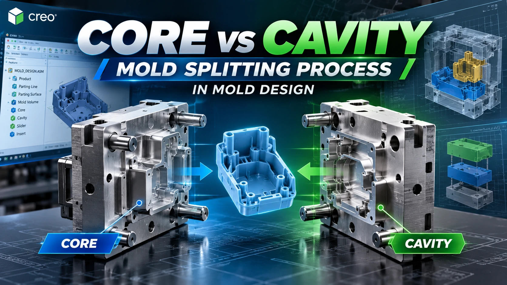
5. Prepare for Core and Cavity Splitting
Checking draft before splitting the mold helps identify surfaces that may complicate core and cavity development. This is especially important before defining mold volumes and extracting tooling components.
6. Identify Areas Requiring Undercut Review
Draft Analysis can highlight surfaces with unfavorable orientations, prompting further investigation of potential undercuts. However, it does not replace a complete undercut or mold-opening interference assessment.
7. Avoid Late Product Geometry Changes
Correcting draft during product development is generally easier than modifying the design after parting surfaces, core/cavity components, ejection systems and manufacturing data have been established.
How Much Draft Angle Is Required?
There is no universal draft angle that applies to every injection-molded product. The appropriate value depends on the plastic material, wall depth, surface texture, dimensional requirements and the mold manufacturer’s recommendations.
| Factor | Draft Consideration |
|---|---|
| Plastic material | Shrinkage and release characteristics |
| Wall depth | Deep walls may require greater draft |
| Surface texture | Textured surfaces may require additional taper |
| Dimensional tolerance | Taper must remain compatible with functional requirements |
| Part geometry | Ribs, bosses and complex features need individual review |
For preliminary design discussions, draft angles around 0.5° to 2° are sometimes considered for relatively smooth surfaces, but this is not a universal specification. Textured surfaces and difficult release conditions may require larger angles. Final values should be confirmed for the specific material and tooling design.
What Is Draft Analysis?
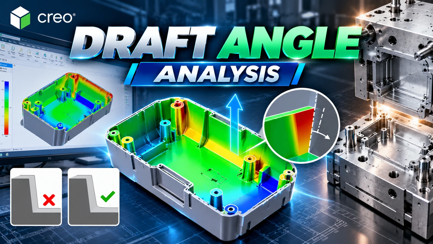
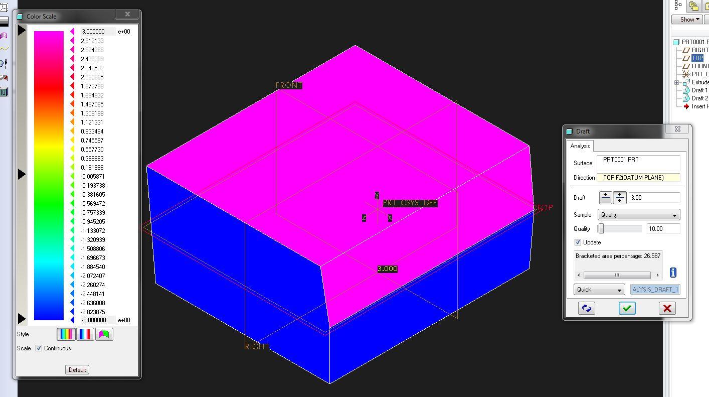
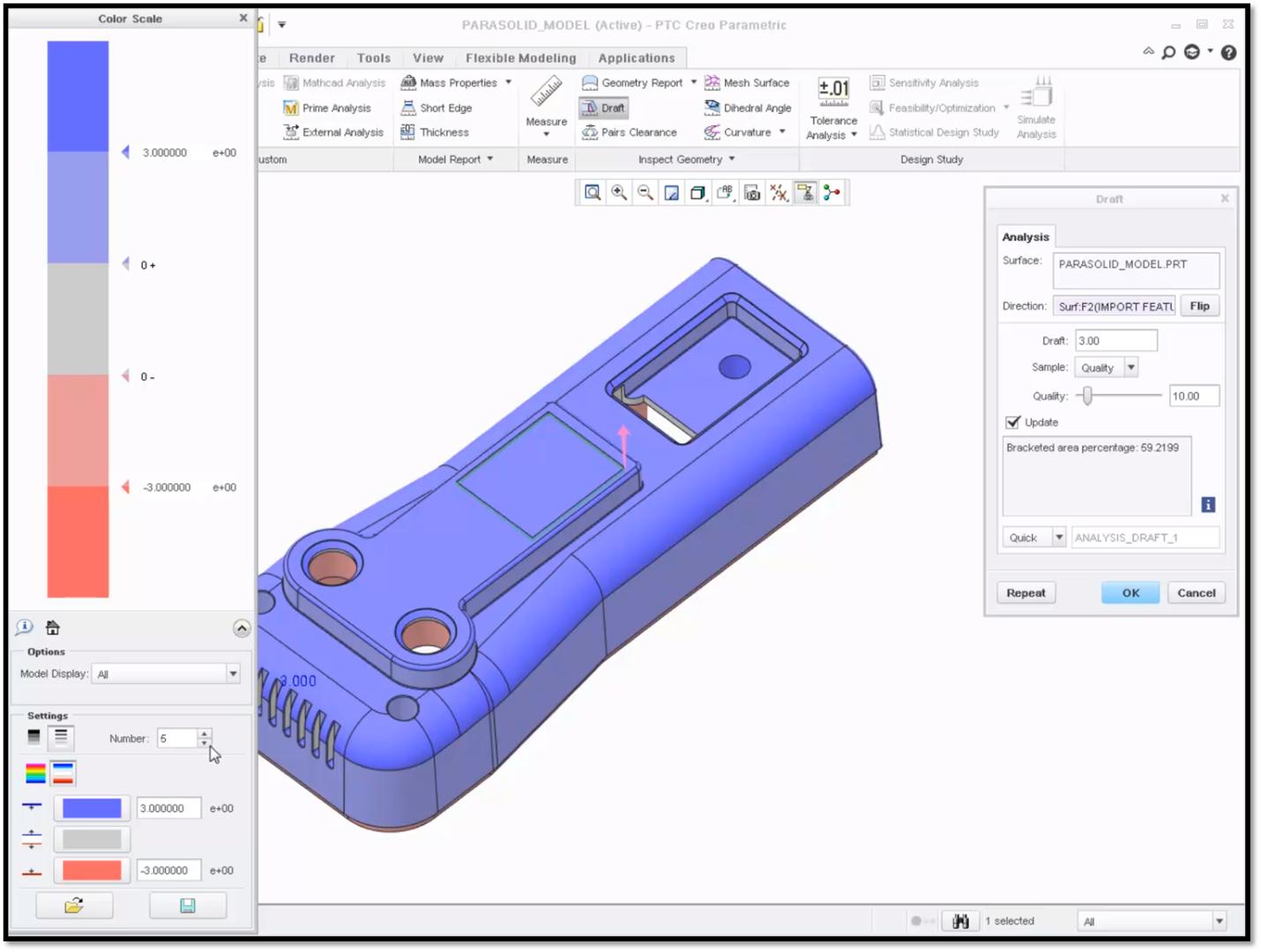
Draft Analysis evaluates surface orientation relative to a selected Pull Direction and target draft angle. Results are commonly displayed as a color map, helping engineers distinguish adequately drafted areas from surfaces that require further evaluation.
PTC Creo supports draft checking on selected surfaces, quilts or suitable solid geometry. The engineer specifies the analysis direction and angle, then reviews the resulting surface-color distribution.
How to Perform Draft Analysis in PTC Creo
Step 1: Prepare the CAD Model
Open the intended product revision in Creo and verify that the geometry is suitable for moldability evaluation.
Step 2: Define the Pull Direction
Select a suitable plane, axis or other supported reference that represents the intended direction of part removal. Verify the direction arrow and reverse it if necessary.
Step 3: Open Draft Analysis
In the Part environment, open Analysis and select Draft. In Mold applications, draft checking is also available through the relevant analysis commands, depending on the Creo version and interface.
Step 4: Select the Geometry
Select the product model or the surfaces to be evaluated. Pay particular attention to deep walls, ribs, bosses, pockets and appearance-critical regions.
Step 5: Specify the Target Draft Angle
Enter the required angle according to the material, product geometry and tooling requirements. Avoid assuming that one value is suitable for every surface.
Step 6: Interpret the Color Map
Review the areas with adequate draft, near-zero draft or unfavorable orientation. Always interpret the results using the active Creo color scale rather than assuming fixed meanings for individual colors.
Step 7: Modify and Recheck
Where appropriate, use Draft Features or other modeling tools to adjust the geometry. Run the analysis again and review the impact on dimensions, adjacent features and parting geometry.
Draft Analysis vs Draft Feature
Draft Analysis is an inspection tool, while Draft Feature modifies geometry by applying taper to selected surfaces. They are complementary capabilities with different purposes.
| Draft Analysis | Draft Feature |
|---|---|
| Evaluates existing geometry | Creates or modifies tapered geometry |
| Displays analytical feedback | Changes the CAD model |
| Identifies areas requiring attention | Supports geometry correction |
| Does not guarantee complete mold release | Does not replace undercut analysis |
Practical Example: Plastic Electronics Enclosure
Consider an electronics enclosure containing external walls, reinforcing ribs, screw bosses and connector openings. Before developing the mold, the engineer defines the Pull Direction and performs Draft Analysis on the 3D product model.
If several vertical walls show insufficient draft, their geometry can be revised before core and cavity development. If a snap-fit feature creates a mechanical obstruction, additional undercut analysis may indicate the need for a slider or a product-design modification.
This approach helps product designers and tooling engineers resolve potential manufacturing issues earlier in the development process.
Does Draft Analysis Replace Undercut Analysis?
No. A surface with sufficient draft does not guarantee that the entire product can be removed from the mold. Hidden geometry, hooks and mechanical interference may still prevent release along the intended direction.
Draft Analysis should therefore be combined with undercut assessment, parting geometry review, mold-opening checks and ejection-system design.
Draft Angle in the PTC Creo Mold Design Workflow
 In a typical mold-design workflow, draft checking is performed after product-model preparation and Pull Direction definition, but before detailed parting-surface and core/cavity development.
The engineering sequence can be summarized as Product Model → Pull Direction → Draft Analysis → Undercut Review → Parting Line → Parting Surface → Core/Cavity → Moldbase → CAM.
PTC Creo supports an integrated product-to-tooling workflow. After the mold geometry has been developed, manufacturers can continue into Creo CAM for CNC toolpath preparation and machining.
For technical guidance, review PTC Creo Draft Checking and PTC Creo Draft Feature.
Common Draft Analysis Mistakes
Incorrect Pull Direction
Using the wrong reference direction can produce results that do not reflect the intended mold-opening strategy.
Using One Angle for Every Surface
Deep walls, textured areas, ribs and other features may have different draft requirements.
Ignoring Internal Features
Ribs, bosses, pockets and internal walls should also be evaluated, not only the external appearance surfaces.
Misinterpreting the Color Scale
Draft colors must be interpreted in the context of the active analysis settings and direction.
Failing to Recheck After Changes
Draft modifications can affect adjacent geometry, functional dimensions and parting decisions. Reanalysis is necessary after relevant model changes.
Frequently Asked Questions About Draft Angle
What Is Draft Angle?
Draft Angle is a deliberate surface taper that helps a molded product release from tooling along a specified direction.
Is a 1-degree draft angle enough?
It may be sufficient for some surfaces, but not all. The required draft depends on material, depth, texture, tolerances and tooling conditions.
Can a part have zero draft?
Some designs may use zero-draft surfaces under specific conditions, but they require careful evaluation of release forces, surface quality and tooling design.
Are Draft Angle and Undercut the same?
No. Draft Angle describes surface taper, while an Undercut is geometry that mechanically obstructs release along the primary mold-opening direction.
Should draft be checked before core and cavity splitting?
Yes. Early checking helps identify surfaces that may require changes before parting geometry and mold volumes are developed.
Does PTC Creo support Draft Analysis?
Yes. Creo provides tools for evaluating draft relative to a selected direction and angle, with graphical feedback on the model.
Does Draft Analysis automatically correct geometry?
No. Draft Analysis evaluates the geometry. Engineers can use Draft Features or other modeling tools to make appropriate modifications.
When should draft be checked?
Draft should be evaluated during product development before detailed tooling, and rechecked after design changes that may affect mold release.
Explore PTC Creo Solutions for Mold Design
Evaluating draft early in the CAD process helps manufacturers identify potential release problems and prepare more reliable product geometry for tooling development.
CADCAM SOFTWARE supports engineering teams in evaluating PTC Creo solutions for product modeling, geometry analysis, mold design and CNC manufacturing. Contact us at 0907 858 000 or info@cadcamsoftware.vn to discuss software requirements, demonstrations and licensing options.