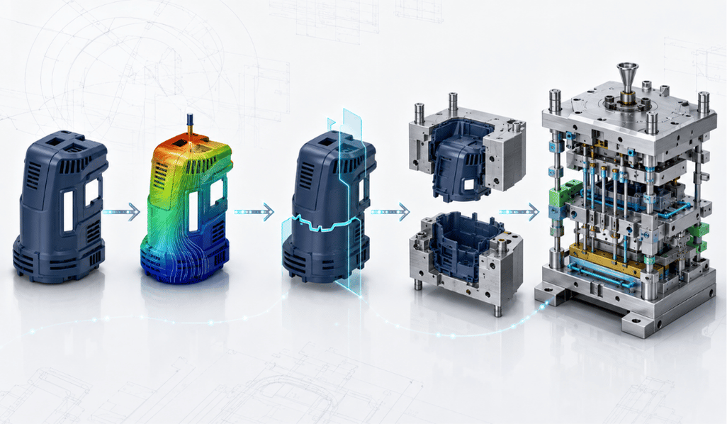
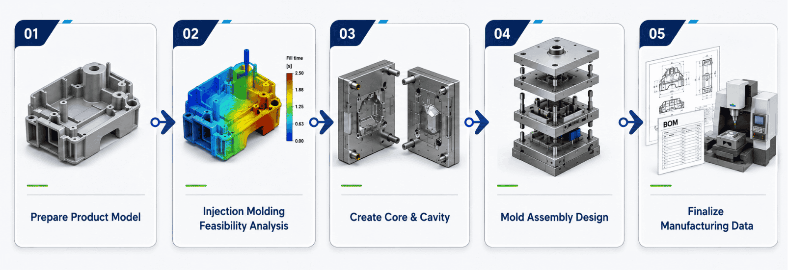
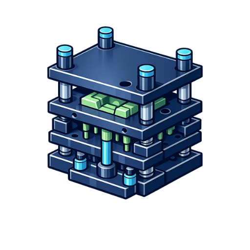
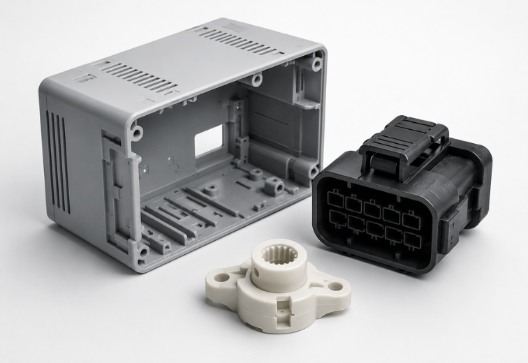
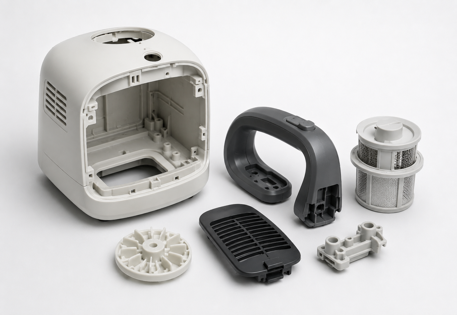
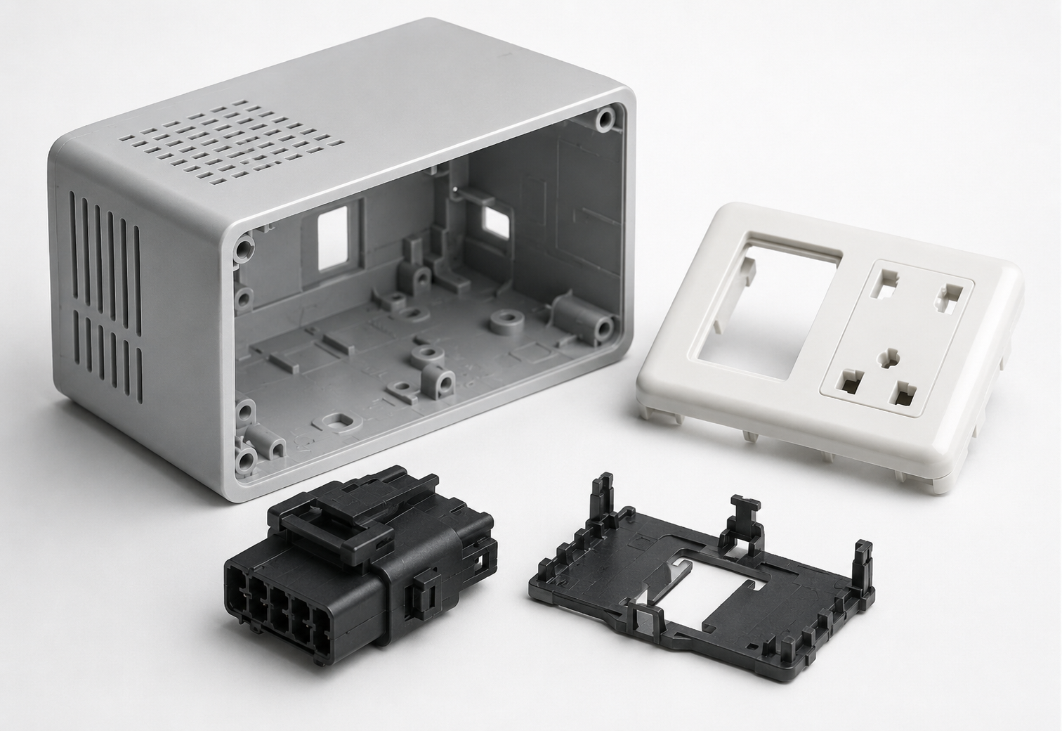
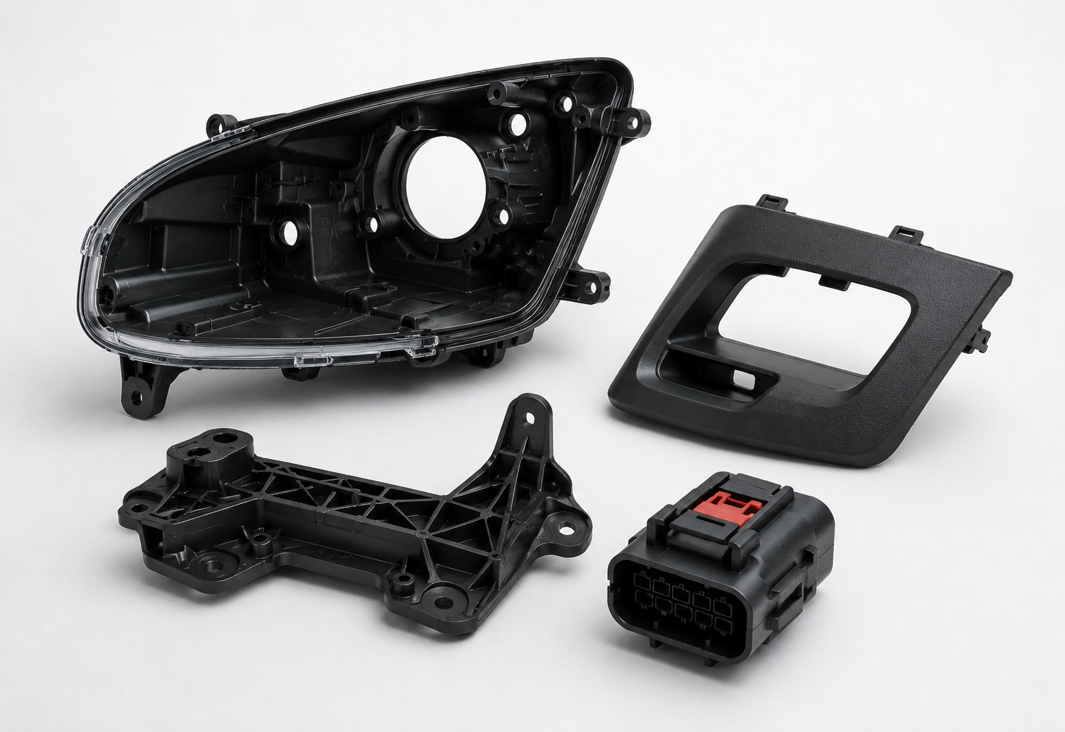
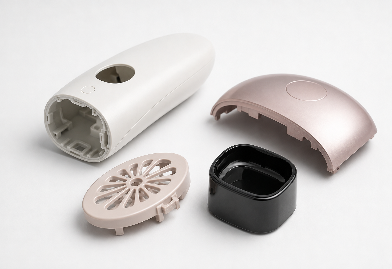
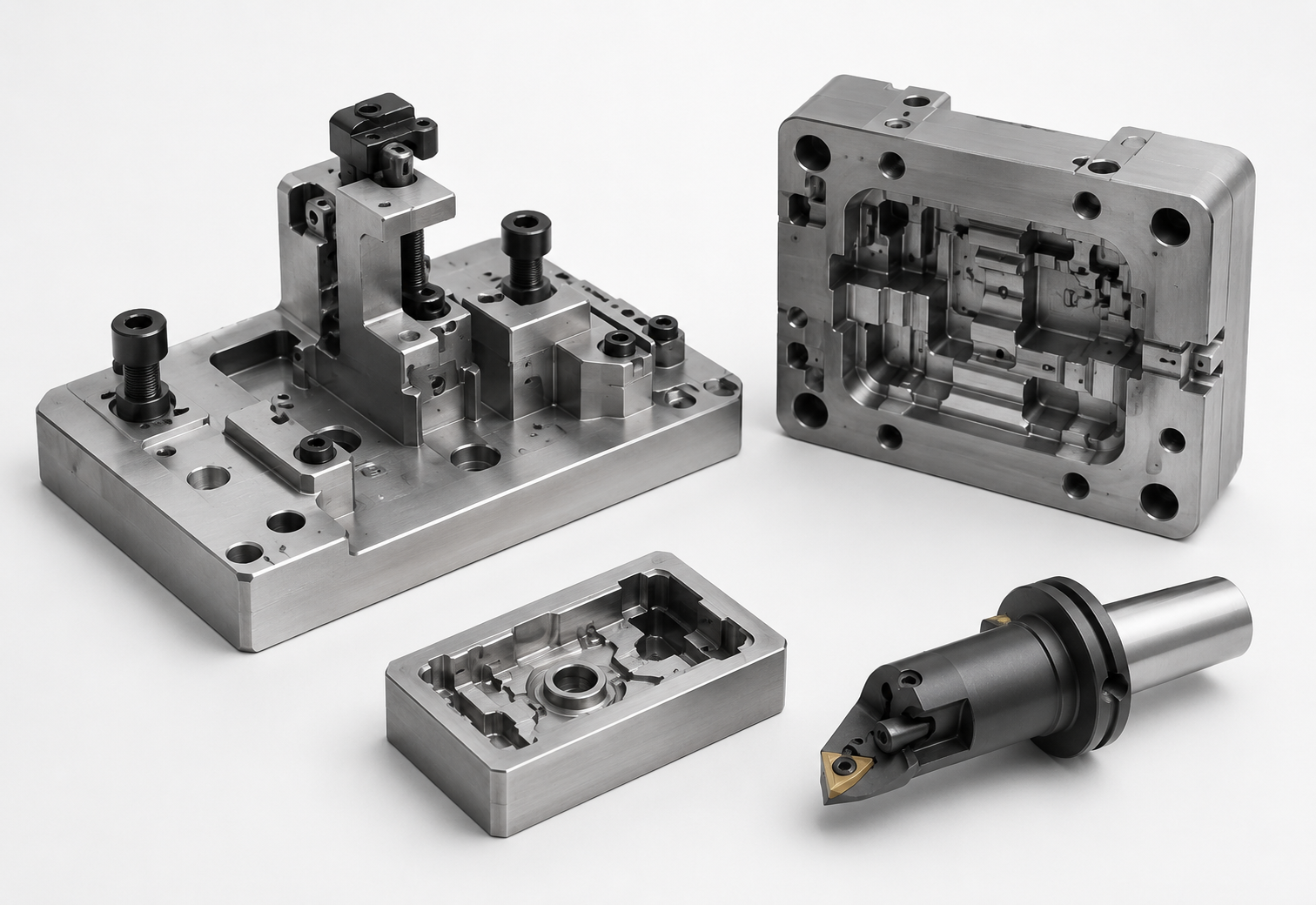
Creo Mold supports manufacturing teams in engineering injection molds directly from native 3D CAD part geometry. PTC’s tooling toolset supports design-for-manufacturability checks, parting direction and draft analysis, parting surface generation, core/cavity splitting, mold base detailing, and preparation of downstream manufacturing (CAM/CNC) data.
With associative parametric architecture, Creo Tool Design maintains a link with the original part model. Changes to source geometry can be reflected in associated mold design data, helping teams reduce manual rework and maintain alignment across parting surfaces, core/cavity inserts, standard components, and production drawings.

Enterprises can implement modular extensions individually or combine them to establish an end-to-end, automated mold development lifecycle.
Engineering Needs | Best-Fit Solutions |
Parting Surface Generation & Core/Cavity Extraction | Creo Tool Design Extension |
Complete Mold Base & Standard Component Detailing | Creo Expert Moldbase |
Plastic Injection Flow & Defect Simulation | Creo Mold Analysis |
All-in-One Synchronized Product & Mold Lifecycle | Creo Injection Molding Suite |
The optimal configuration should be selected based on mold tool complexity, multi-cavity layout, existing engineering workflow, and the number of concurrent CAD/CAM seats.
Creo Mold is the collective name for PTC’s specialized modular suite—including Creo Tool Design (TDO), Creo Expert Moldbase (EMX), and Creo Mold Analysis (CMA)—dedicated to injection mold engineering, flow simulation, and tooling automation within PTC Creo
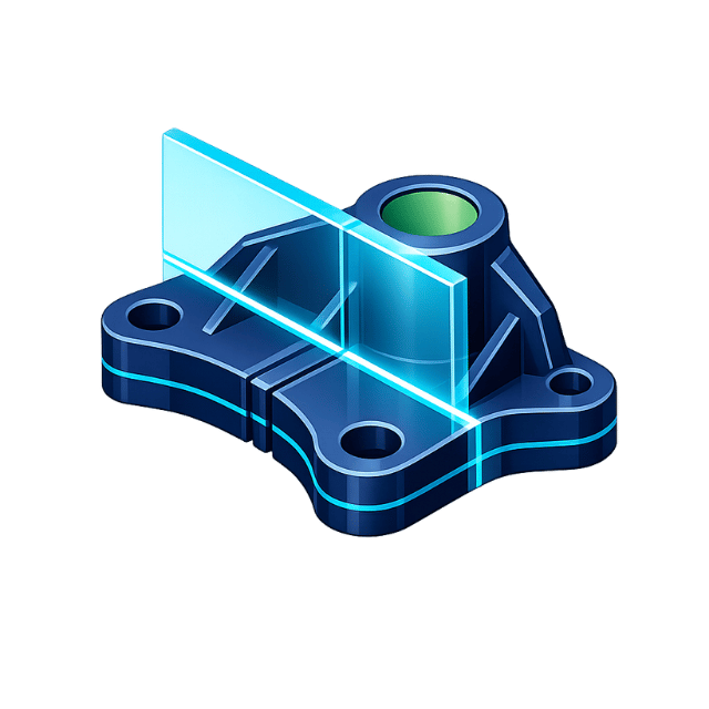
It specializes in core/cavity splitting, associative parting surface creation, shrinkage compensation, draft verification, and extracting mold components directly from 3D part geometry.
While Tool Design focuses on geometry splitting and core/cavity insert generation, Expert Moldbase (EMX) automates the entire mechanical mold base structure—integrating standard component libraries (plates, ejectors, cooling circuits, sliders) and automated 2D tooling drawings.
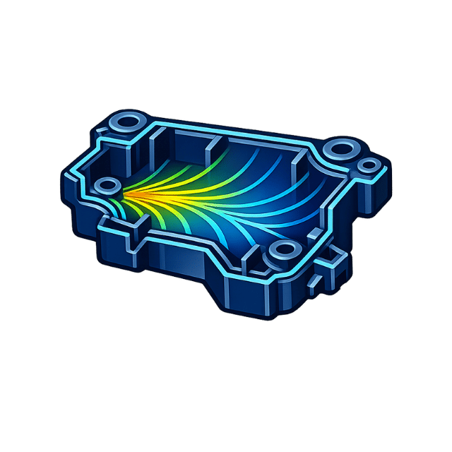
CMA predicts potential manufacturing defects such as short shots (incomplete filling), weld/meld lines, air traps, sink marks, high clamping tonnage requirements, and non-uniform cooling gradients before tooling fabrication.