

PTC Creo CAD – Professional 3D CAD Software for Product Design

PTC Creo CAD provides powerful parametric 3D modeling, assembly design, engineering drawings, and advanced product design capabilities for mechanical engineering and manufacturing companies.
REQUEST A QUOTE →

PTC Creo CAD – Professional 3D CAD Software for Product Design

PTC Creo CAD provides powerful parametric 3D modeling, assembly design, engineering drawings, and advanced product design capabilities for mechanical engineering and manufacturing companies
REQUEST A QUOTE→

What is PTC Creo CAD?

PTC Creo CAD is a professional 3D CAD solution for mechanical design and product development. It enables engineers to create precise 3D models, manage complex assemblies, generate engineering drawings, and prepare product data for downstream engineering and manufacturing processes

Comprehensive 3D CAD Design Capabilities​

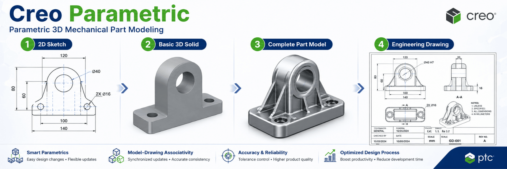
3D Part Modeling
Create accurate parametric models for simple and complex mechanical components.

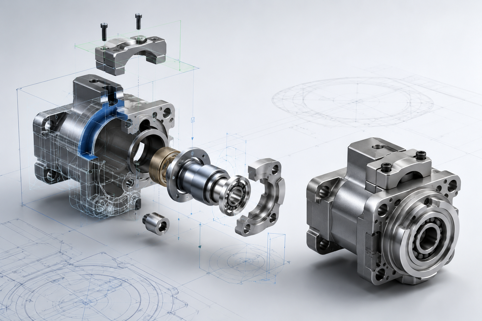
Assembly Design
Build and manage product assemblies while checking component relationships and interference.

2D Engineering Drawings
Generate associative engineering drawings from 3D models according to industry standards.

Surface Design
Create complex surfaces and freeform geometry for advanced product development.

Sheet Metal Design
Design sheet metal parts with manufacturing-ready geometry and documentation.

Creo supports parametric/direct modeling, complex surfacing, sheet metal, drawings and assembly management.

What is Creo CAD? Capabilities of Creo Parametric​

Creo CAD is a Computer-Aided Design (CAD) solution used to create, modify, and manage digital product designs and engineering data. At the core of the solution is Creo Parametric, PTC’s primary parametric 3D CAD application for mechanical design and product development.

Core Design Capabilities of Creo CAD

  • 3D Part Modeling: Create mechanical components using solid modeling, surface modeling, and multi-body design capabilities.
  • Large Assembly Design: Build and manage complex assemblies containing large numbers of components, perform interference detection, and conduct basic mechanism analysis and simulation.
  • 2D Engineering Drawings: Automatically generate associative 2D engineering drawings from 3D models, including dimensions, Geometric Dimensioning & Tolerancing (GD&T), surface finish symbols, annotations, and Bills of Materials (BOMs).
  • Sheet Metal Design: Design sheet metal parts, enclosures, bends, corner treatments, and automatically generate flat patterns for downstream manufacturing.
  • Advanced Surface Design: Create complex and freeform surfaces for industrial design, product styling, and aerodynamic surface development.
  • Multi-CAD Data Exchange: Import and work with CAD data from multiple systems and standard formats, including STEP, IGES, SOLIDWORKS, CATIA, and Siemens NX, supported by Creo Unite Technology.

6 Key Features of PTC Creo CAD

1. Parametric Modeling
Build 3D models based on dimensions, constraints, features, and geometric relationships, enabling flexible design changes while preserving design intent.

2. Versatile 3D Part Design
Create complex product geometry using powerful solid, surface, and multi-body design capabilities.

3. Large Assembly Management
Build and manage complex assemblies with tools designed to improve visualization, navigation, and engineering productivity.

4. Associative Engineering Drawings
Maintain associativity between 3D models and 2D drawings. Design changes can propagate to associated engineering documentation.

5. Advanced Surfacing
Use Freestyle and advanced surface modeling tools to create complex geometry for industrial design and product styling.

6. Multi-CAD Compatibility
Use Creo Unite Technology to work with data from other major CAD systems and reduce unnecessary file translation

Comprehensive Creo CAD Design Capabilities

Part Modeling

Create solid and multi-body 3D mechanical components.
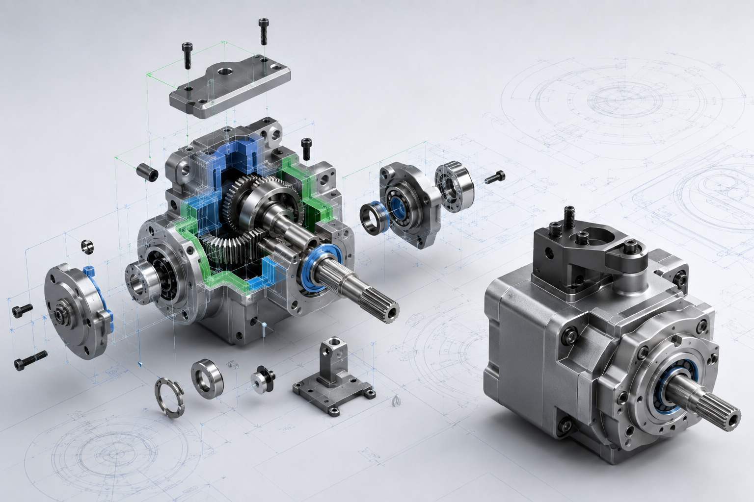
Assembly Design

Build product assemblies and perform static and dynamic interference checks.
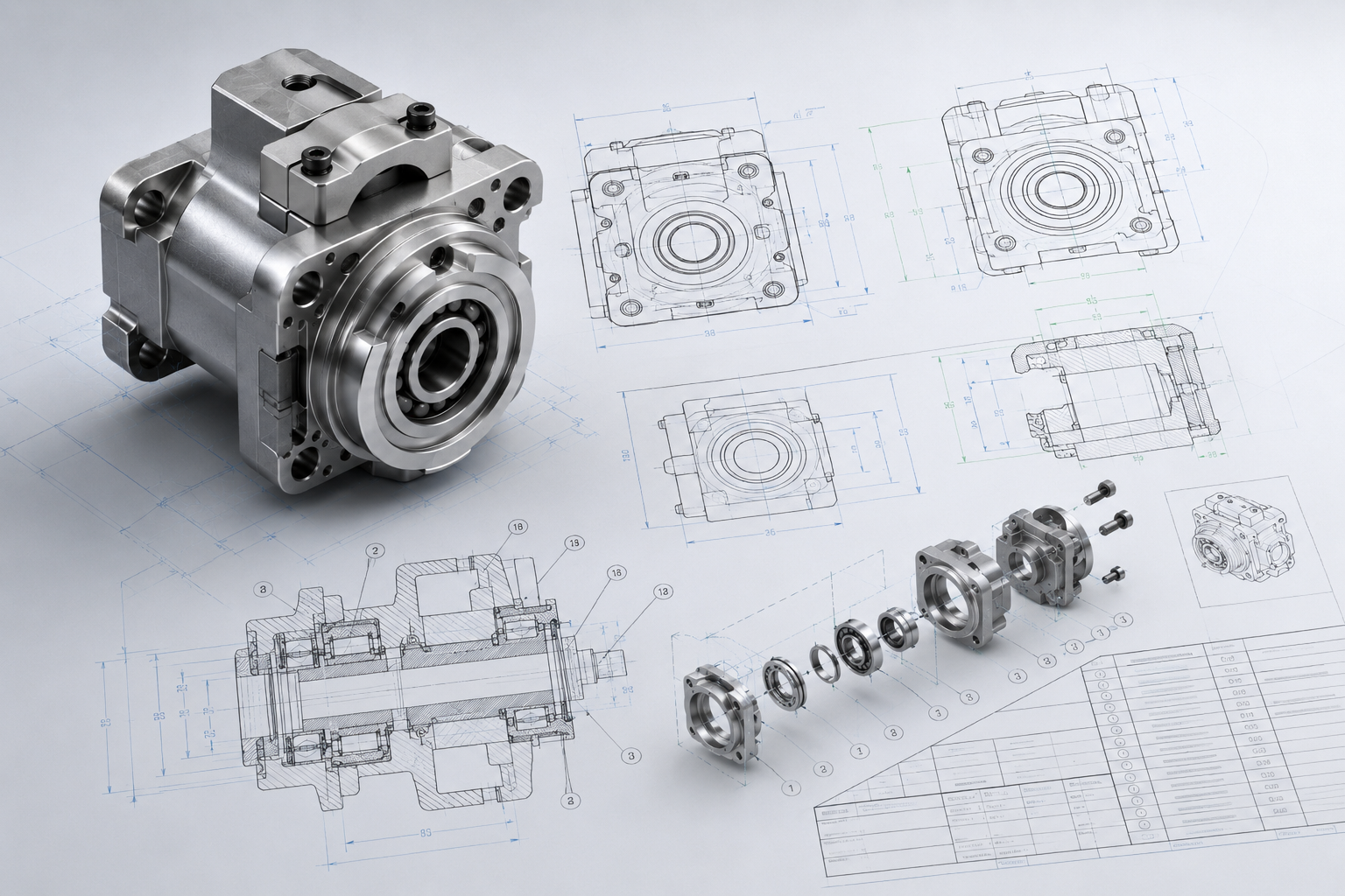
Detailed Drawings

Create 2D engineering drawings with dimensions, tolerances, annotations, and BOMs
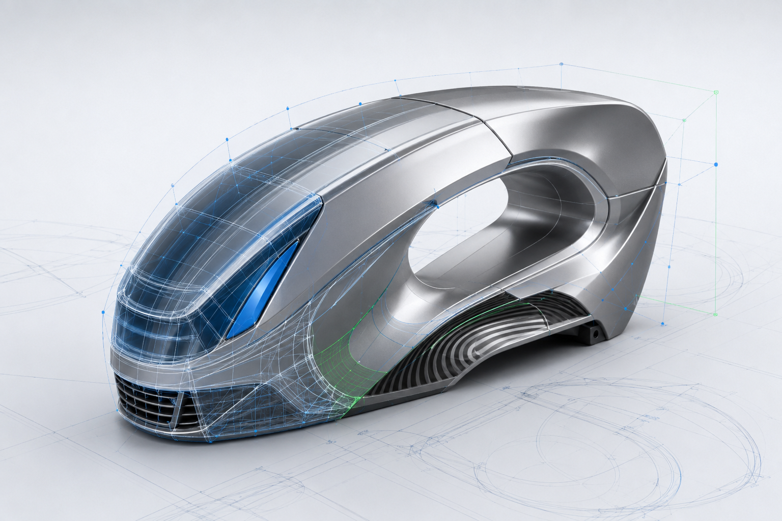
Surfacing (Freeform & Technical)

Create freeform and complex technical surfaces for industrial design applications.
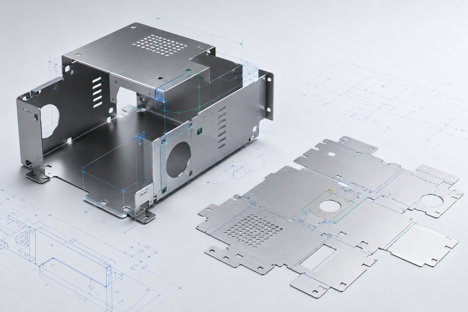
Sheet Metal Design

Design sheet metal parts, define bend parameters, and automatically generate flat patterns.
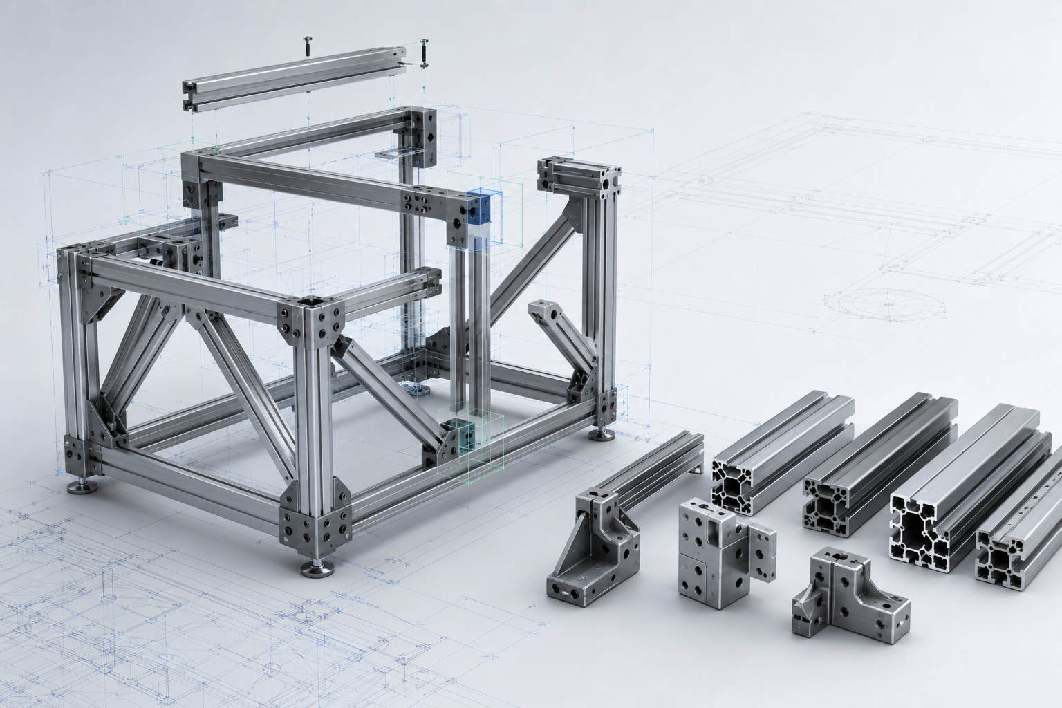
Advanced Framework (AFX)

Design structural frames, steel structures, and standardized profile systems.
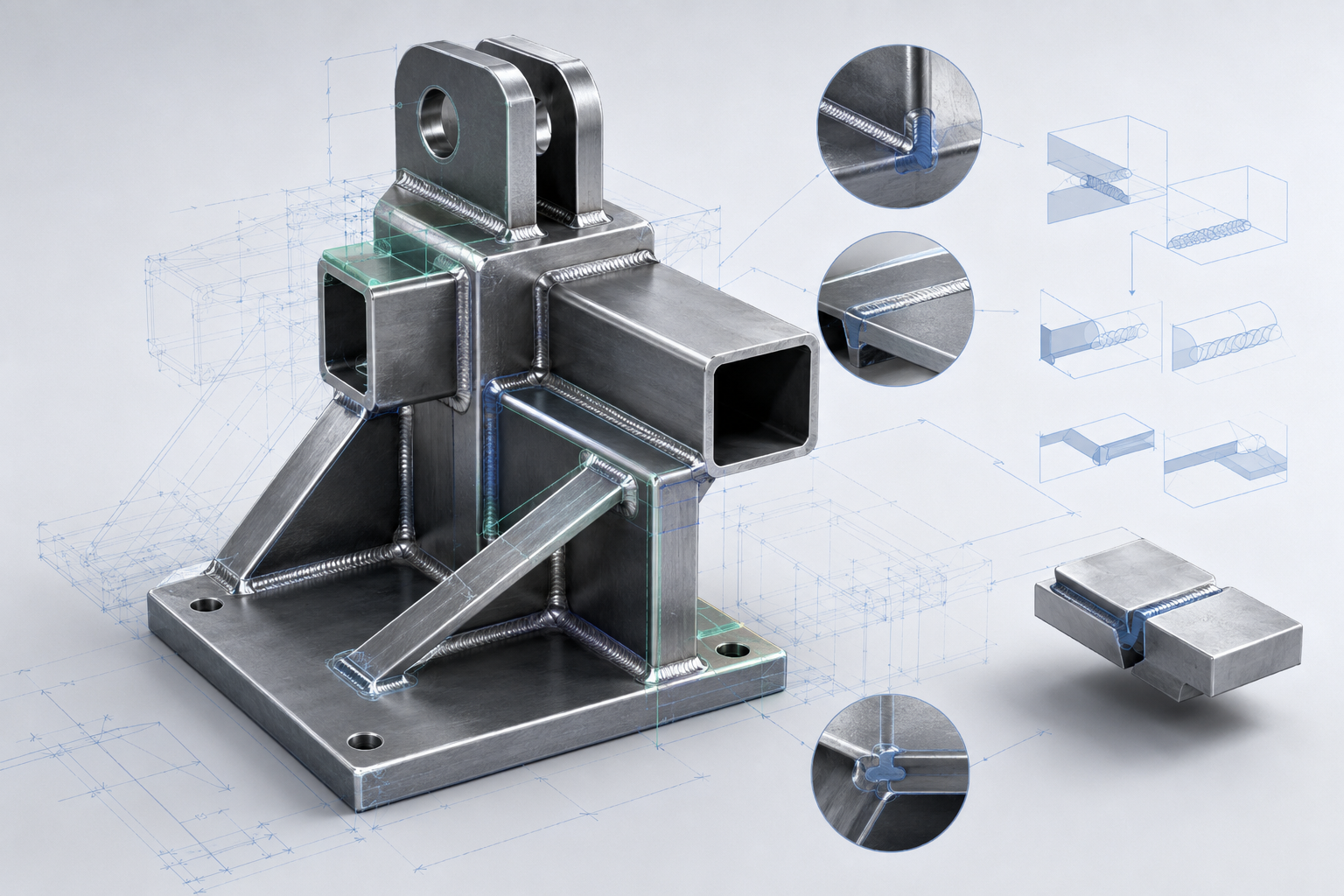
Welding Design

Define welds, calculate related material requirements, and document welding symbols in 3D and 2D.
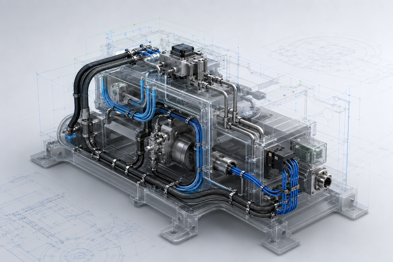
Piping & Cabling

Route rigid and flexible piping systems and electrical cabling.
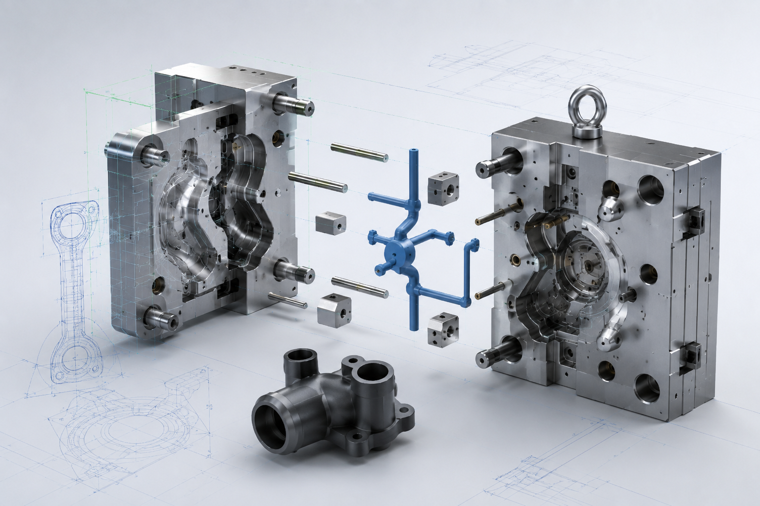
Mold Design & Casting

Develop mold geometry, parting surfaces, cores and cavities, and components for casting applications.
Standard Product Design Workflow with Creo CAD

01. Define Engineering Requirements
Establish key design parameters, including dimensions, materials, functional requirements, and engineering constraints.

02. Concept Design
Develop initial layouts and define the product architecture and operating principles.

03. Detailed 3D Modeling
Use Part, Sheet Metal, and Surfacing tools to create accurate component geometry.

04. Assembly Design & Verification
Assemble individual components into a complete product and perform interference and fit checks.

05. Engineering Documentation
Generate associative 2D drawings and add dimensions, tolerances, manufacturing symbols, and BOMs.

06. Release for Downstream Engineering
Prepare product data for simulation, CAM programming, manufacturing, or PDM/PLM management

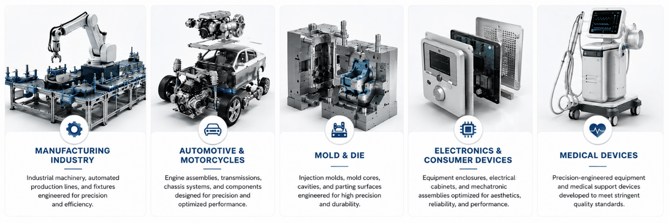
Ứng dụng thực tế của phần mềm Creo CAD theo ngành

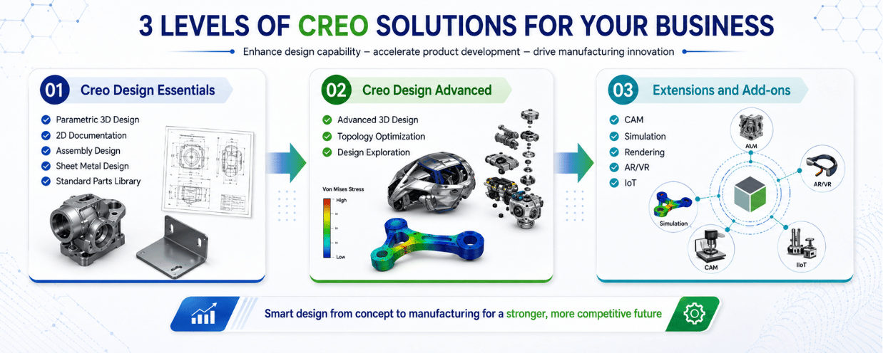
Choose the Right Creo CAD Package

PTC offers flexible Creo Design Packages to address different engineering requirements and organizational needs.

Creo Design Essentials
Core CAD capabilities for Part Design, Assembly Design, Detailed Drawings, Sheet Metal, and Framework Design, suitable for general mechanical design applications.

Creo Design Advanced / Advanced Plus
Extended capabilities for organizations requiring more advanced design, surfacing, assembly, and engineering functionality.

Optional Extensions
Additional modules such as Mold Design Extension, Piping & Cabling Extension, and Creo Flexible Modeling Extension (FMX) can be added based on specific engineering requirements.

Contact CADCAM Software for a requirements assessment to identify the appropriate Creo configuration and avoid investing in unnecessary functionality.

WHY CADCAM SOFTWARE?

Why Choose CADCAM Software for Creo CAD?

CADCAM Software provides Creo software licensing, implementation, training, and technical support for engineering and manufacturing companies in Vietnam.

Solution Configuration Consulting
Assess actual engineering requirements to recommend the appropriate Creo package and configuration.

Product-Based Demo
Evaluate Creo capabilities using representative customer parts, assemblies, or product data.

Implementation & Professional Training
Training programs from fundamental to advanced Creo applications, including 3D Modeling, Sheet Metal, Detailed Drawings, and advanced design workflows.

Technical Support
Technical assistance for software deployment, troubleshooting, operation, and software updates.

Request a Consultation & Software Quote

Frequently Asked Questions About Creo CAD

Creo CAD is a parametric 3D CAD solution developed by PTC for product design and mechanical engineering.

Creo refers to PTC’s broader product development platform, while Creo Parametric is its core parametric 3D CAD application for mechanical product design.

Yes. Creo provides Sheet Metal Design capabilities for creating sheet metal components, defining bends and manufacturing features, and generating accurate flat patterns.

System requirements depend on the Creo version, model complexity, assembly size, and engineering workload. For production deployment, CADCAM Software should recommend hardware based on the customer’s actual use case.