
What Is Creo Parametric?
For additional product information and capabilities, visit the official PTC Creo website.
Applications in 3D Mechanical Design
Creo Parametric is a parametric 3D CAD application within the PTC Creo platform, developed for mechanical design and product development. It enables engineers to create 3D parts, assemblies and engineering drawings using dimensions, parameters, geometric constraints and design relationships.
A key advantage of Creo Parametric is its ability to capture design intent. Instead of treating 3D geometry as independent objects, engineers can establish relationships between features so that related elements can respond intelligently when a design changes.
Companies evaluating professional CAD solutions can explore PTC Creo Parametric software and the broader PTC Creo CAD solution available from CADCAM Software.
What Is Creo Parametric?
Creo Parametric is the core parametric 3D CAD application in the PTC Creo product development ecosystem. It is designed for engineers who need to create precise mechanical components, assemblies and product documentation while maintaining engineering relationships throughout the design process.
The technology evolved from Pro/ENGINEER (Pro/E), which introduced feature-based parametric solid modeling to the CAD industry.
In a parametric model, dimensions and features can be connected through predefined relationships. If an engineer changes a critical dimension, dependent geometry can update according to the established design intent.
Are Creo and Creo Parametric the Same?
The terms are closely related but have different meanings.
PTC Creo refers to the broader product development platform and engineering ecosystem, while Creo Parametric is its core parametric 3D CAD application for mechanical product design.
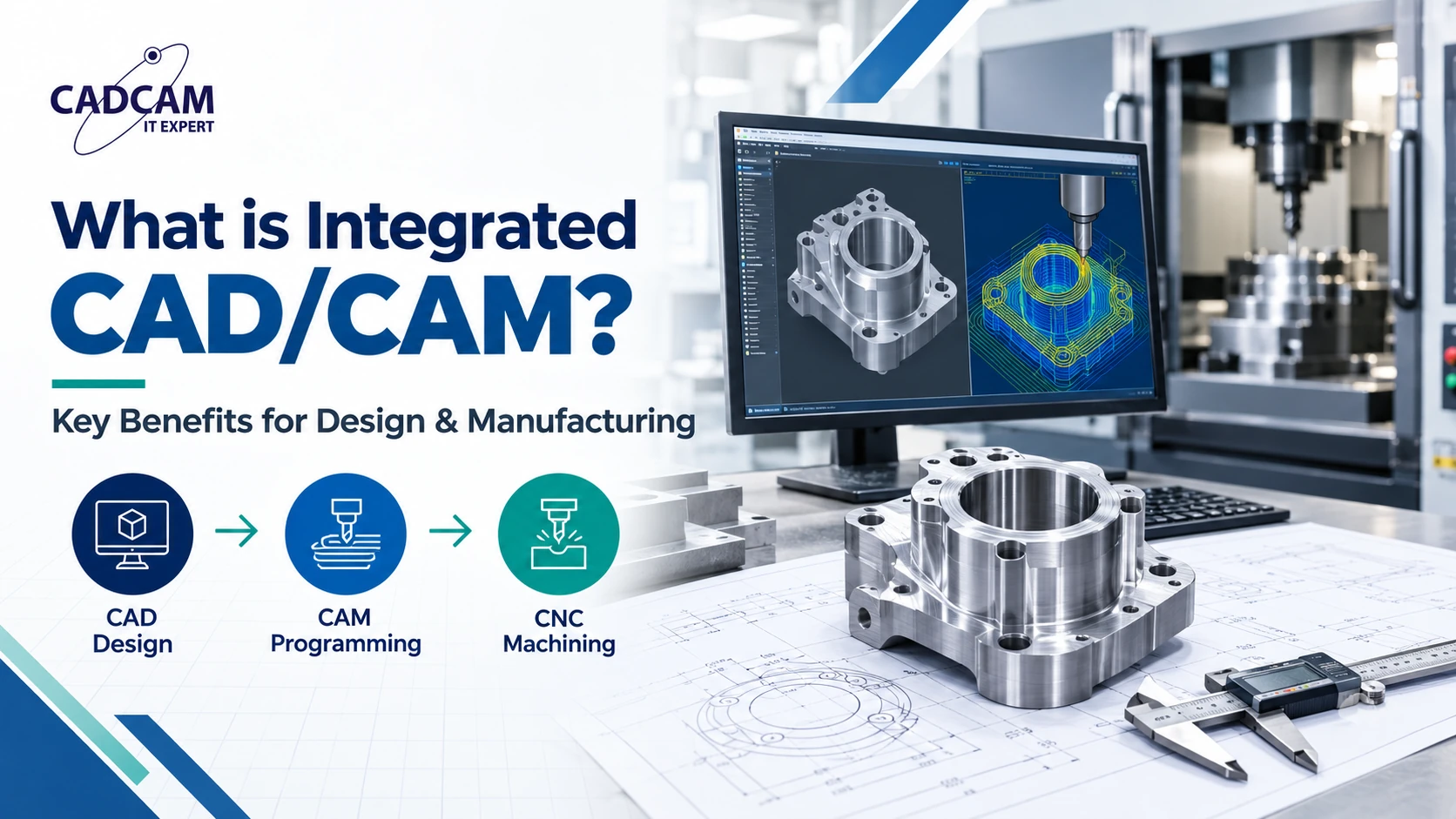
Depending on engineering requirements, the Creo environment can extend beyond CAD into simulation, tooling, mold design and CNC manufacturing.
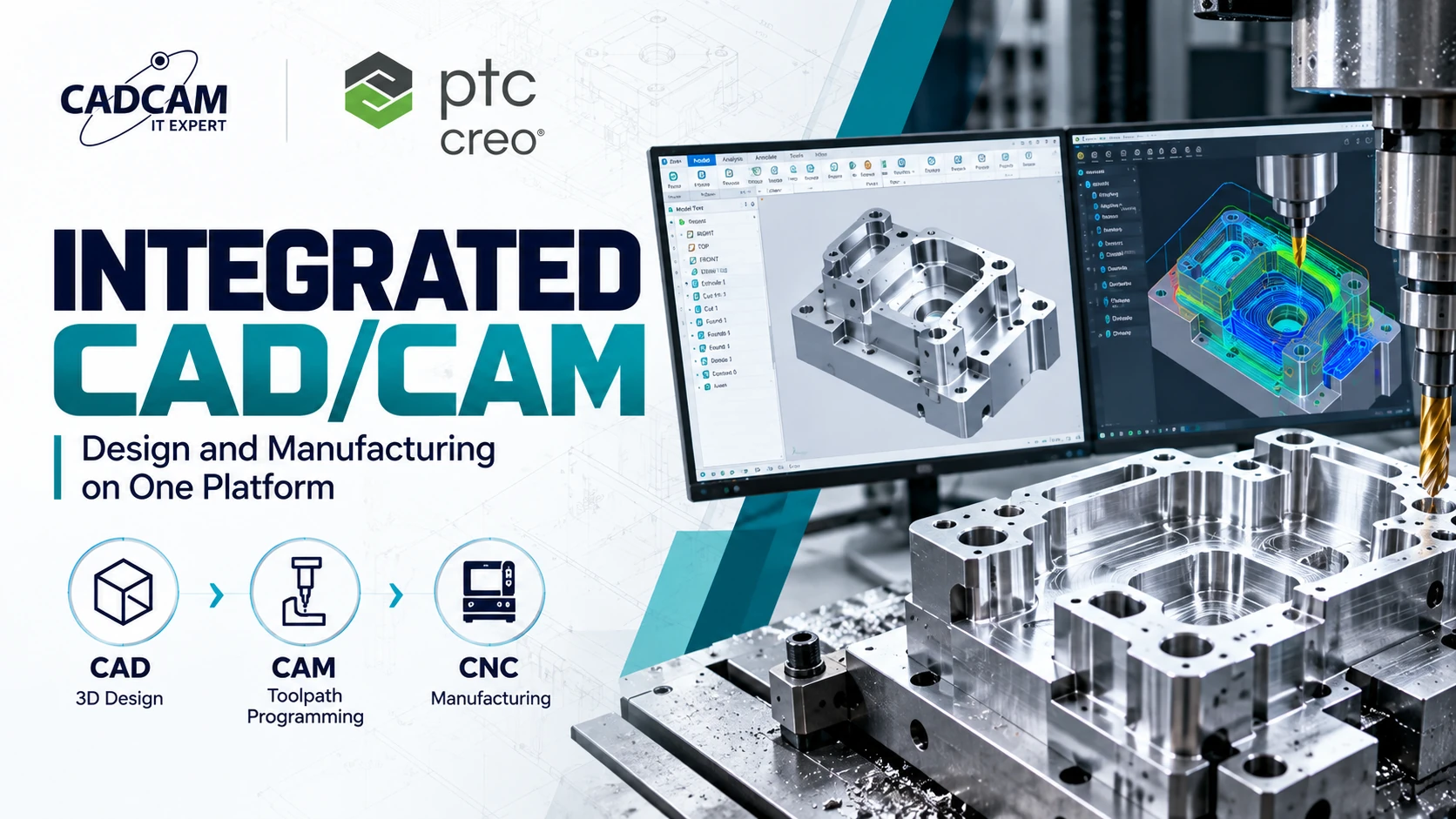
For example, tooling teams can continue product development with Creo Mold, while manufacturing teams can use Creo CAM to connect CAD data with CNC programming workflows.
How Does Parametric Modeling Work in Creo Parametric?
Parametric modeling enables engineers to build models using features, dimensions, parameters, constraints and relationships rather than treating geometry as completely independent entities.
Dimensions
Engineers can control lengths, diameters, radii, angles and other geometric values through defined dimensions.
Constraints
Geometric relationships such as parallel, perpendicular, concentric, tangent and symmetric conditions help preserve model behavior when dimensions change.
Feature-Based Modeling
Features such as Extrude, Revolve, Hole, Round, Chamfer and Pattern are created in a structured design process and can depend on other features.
Design Intent
Design intent defines how the model should behave when engineering changes occur. Capturing design intent correctly can make future modifications faster and more predictable.
Associativity
Creo maintains relationships across parts, assemblies and engineering drawings. Changes made to the design can therefore be reflected across associated product information.
Key 3D Mechanical Design Capabilities
3D Part Modeling
Creo Parametric enables engineers to create mechanical components using feature-based and parametric modeling tools. This supports both simple components and complex product geometry.
Assembly Design
Engineers can combine individual components into product assemblies while controlling component positioning, constraints and product structure.
This capability is particularly important for industrial machinery, equipment and products consisting of many interconnected components.
2D Engineering Drawings
Associative engineering drawings can be generated from 3D models with views, sections, dimensions, tolerances and annotations required for downstream manufacturing.
Sheet Metal Design
Creo supports sheet metal product development, including bends, flanges and manufacturing-oriented features, as well as flat patterns for downstream production.
Surface Modeling
Solid and surface modeling capabilities can be combined to develop products requiring complex technical or freeform geometry.
Multi-CAD Collaboration
Engineering companies frequently receive CAD data from customers, suppliers and partners using different design systems. Creo provides Multi-CAD capabilities to support collaboration and reduce unnecessary data conversion across engineering workflows.
Applications of Creo Parametric in 3D Mechanical Design
Industrial Machinery and Equipment
Creo can be used to design shafts, housings, frames, mechanisms, machine components and complete industrial equipment assemblies.
Parametric design is particularly valuable for machine builders producing multiple sizes or configurations of a common product architecture.
Mechanical Product Development
Creo Parametric supports product development from initial engineering concepts through detailed 3D modeling and manufacturing documentation.
Mold and Tooling Design
Product geometry created in Creo Parametric can become the foundation for downstream mold and tooling development, including draft analysis, parting definition, core/cavity development and moldbase design.
Sheet Metal Products
Typical applications include machine enclosures, cabinets, brackets, panels and other fabricated sheet metal products.
Automotive and Transportation Components
Parametric part modeling, assemblies and surfacing make Creo suitable for the development of mechanical components and product structures used in transportation applications.
Electronics and High-Tech Products
Mechanical engineers can develop housings, enclosures, brackets and structural components for electronics and high-tech products while coordinating geometry and packaging requirements.
Benefits of Creo Parametric for Engineering Companies
Better Design Change Control
Parameters and engineering relationships enable design teams to maintain predefined logic as products evolve.
Design Reuse
Parametric models can support product families and variants, reducing the need to recreate similar products from scratch.
Consistency Between 3D Models and Drawings
Associativity helps maintain consistency between product geometry and related engineering documentation.
Connection Between Design and Manufacturing
CAD data can continue downstream into simulation, mold development, CAM programming and other manufacturing processes.
Product Data and Lifecycle Management
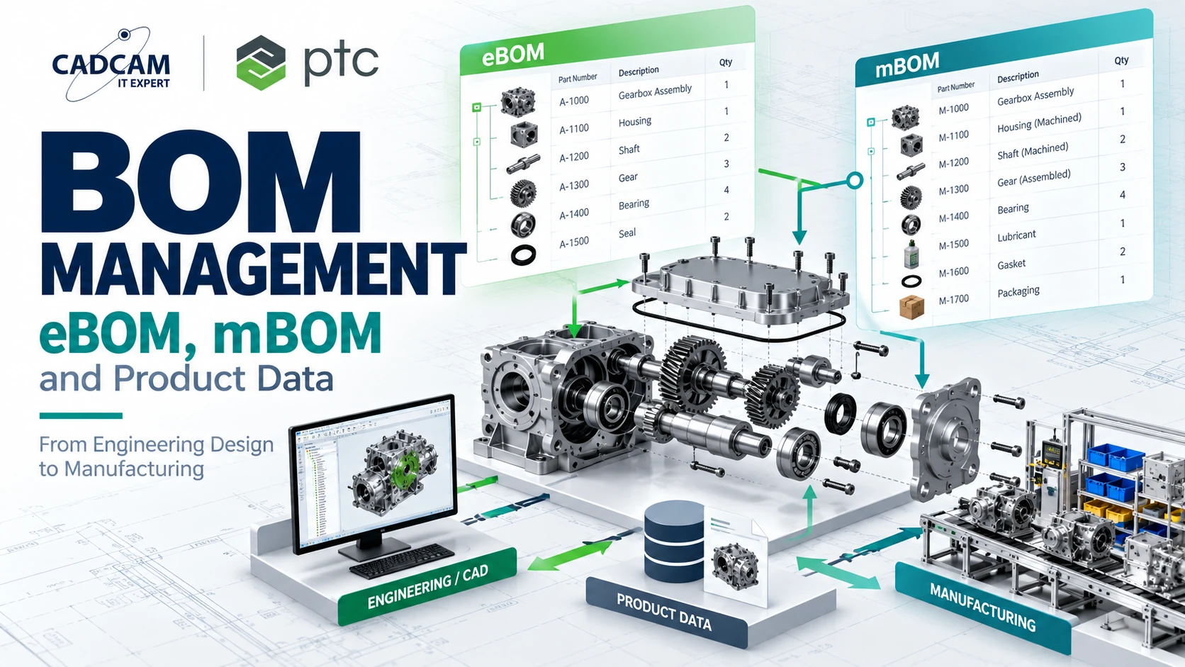
Organizations requiring structured product data, revisions and engineering collaboration can connect Creo workflows with PTC Windchill PLM.
Typical 3D Mechanical Design Workflow with Creo Parametric
- Define engineering requirements: Establish functional, dimensional, material and manufacturing requirements.
- Define design intent: Identify critical parameters and engineering relationships.
- 3D part modeling: Create individual components using parametric features.
- Assembly design: Build the complete product structure and define component relationships.
- Design validation: Review geometry, fit and engineering requirements.
- Engineering documentation: Generate drawings and manufacturing information.
- Downstream engineering: Continue product data into simulation, tooling, CAM or PLM workflows.
Who Uses Creo Parametric?
- Mechanical design engineers
- Product development engineers
- R&D teams
- Machine builders
- Tooling and mold engineers
- Industrial manufacturing companies
- Organizations standardizing 3D engineering data
Creo Parametric vs. Creo Elements/Direct
Creo Parametric is based primarily on parametric and feature-based modeling, where geometry is controlled through dimensions, constraints, relationships and feature history.
Creo Elements/Direct focuses on direct modeling, allowing engineers to modify geometry directly without depending on a traditional feature-history structure.
Parametric modeling is particularly useful when engineering teams need to preserve design intent, create product families or manage configurable designs over multiple design iterations.
From Creo Parametric to Digital Product Development
Creo Parametric can provide the core 3D engineering definition, while the broader product development process can extend into:
3D CAD → Simulation → Mold & Tooling → CAM/CNC → PLM
Explore the PTC software portfolio to identify the appropriate engineering and product lifecycle solutions for your organization.
Frequently Asked Questions About Creo Parametric
What is Creo Parametric?
Creo Parametric is PTC’s parametric 3D CAD application for mechanical design and product development. It supports part modeling, assembly design, engineering drawings, sheet metal, surfacing and related engineering workflows.
What is the difference between Creo and Creo Parametric?
Creo refers to PTC’s broader product development platform, while Creo Parametric is the core parametric 3D CAD application used for mechanical product design.
Can Creo Parametric be used for machine design?
Yes. Creo Parametric can be used to develop mechanical parts, assemblies, industrial machinery, equipment and complex mechanical product structures.
Does Creo Parametric support sheet metal design?
Yes. Creo provides sheet metal design capabilities for developing bends, flanges and manufacturing-oriented sheet metal geometry, including flat patterns.
Can Creo Parametric be used for mold design?
Creo Parametric product geometry can be used as the foundation for mold development. Specialized Creo tooling capabilities extend the workflow into parting surfaces, core/cavity development and moldbase design.
Does Creo support CAM?
Yes. Product data created in Creo can be used in Creo CAM workflows for integrated CAD/CAM and CNC manufacturing applications.
PTC Creo Parametric Consulting and Licensing
Selecting a CAD solution should be based on actual engineering requirements, including product complexity, assembly size, surfacing, sheet metal, tooling, manufacturing and product data management.
CADCAM Software provides PTC Creo solutions for engineering and manufacturing companies. Explore PTC Creo Parametric or contact CADCAM Software to discuss the appropriate software configuration for your engineering workflow.