What Are Core and Cavity? Mold Splitting Process Explained
Core and Cavity are the primary tooling regions that create the geometry of an injection-molded product. Defining the correct pull direction, parting line, parting surface and Core/Cavity split has a direct impact on mold release, tooling structure, surface quality and downstream manufacturing.
For a mold designer, splitting a mold involves much more than dividing a 3D block into two halves. Engineers must first evaluate product geometry, pull direction, draft angles, undercuts, parting geometry and shut-off conditions. Complex products may also require sliders, lifters or inserts to release geometry that cannot move along the primary mold-opening direction.
PTC Creo provides dedicated mold-design workflows that enable engineers to develop this tooling geometry directly from the 3D product model while maintaining relationships between product and tooling data.
What Are Core and Cavity?
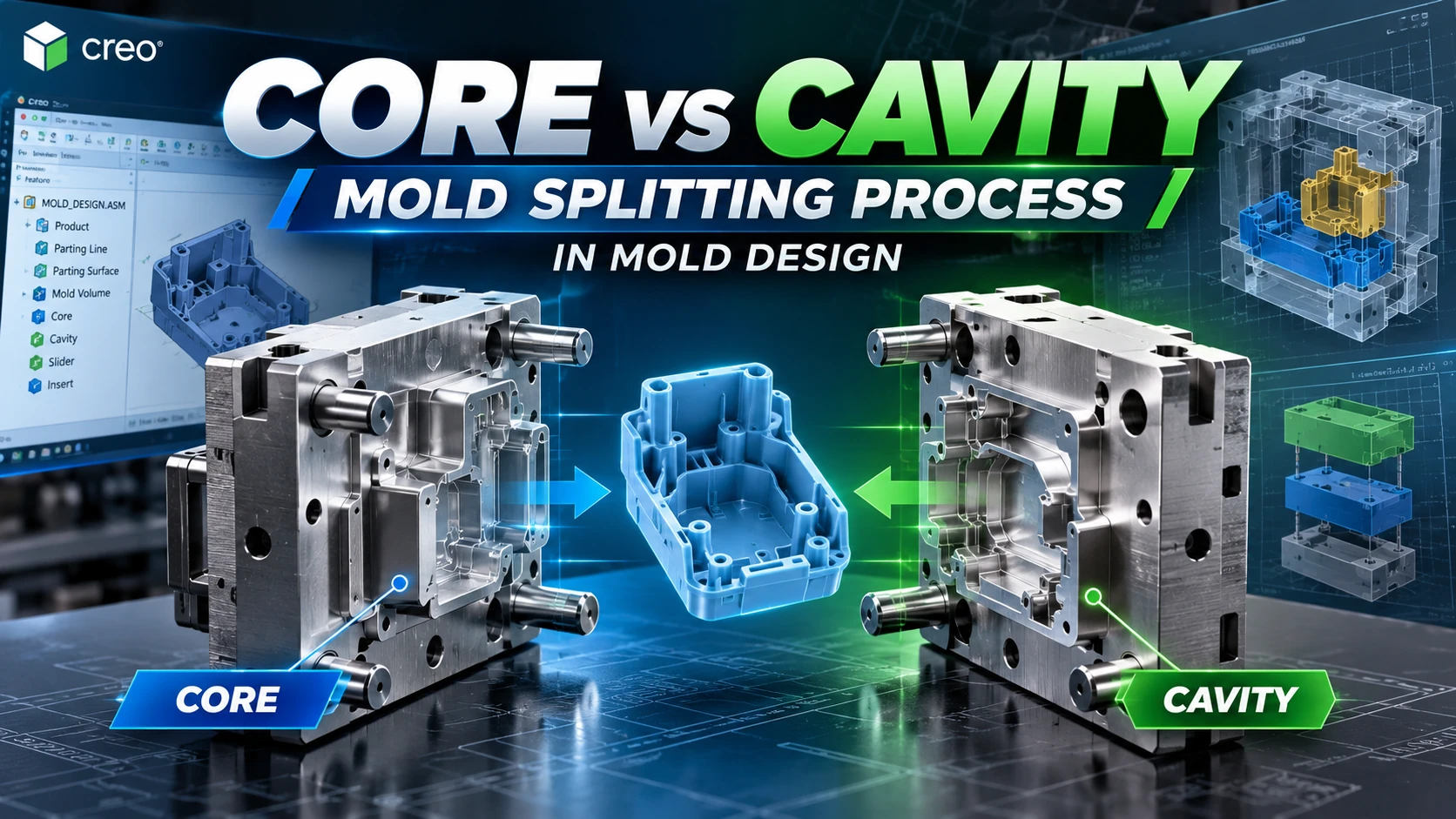
Core and Cavity are the two primary geometric regions that combine to form the molding space responsible for producing the part geometry. When the mold closes, their corresponding surfaces define the shape into which molten material is injected and subsequently cooled.
The terms should not simply be interpreted as the upper and lower halves of a mold. Their actual geometry and location depend on the product, mold-opening strategy, ejection requirements and overall tooling architecture.
What Is the Core in a Mold?
The Core generally forms internal, recessed or corresponding product geometry that requires tooling to project into the molded component. It may be manufactured as a single core block or divided into multiple core inserts depending on machining, maintenance, cooling and tooling requirements.
What Is the Cavity in a Mold?
The Cavity is the corresponding mold region that forms another portion of the product geometry. In many injection-molded products, cavity surfaces are closely associated with exterior or appearance-critical surfaces, although this should not be treated as an absolute rule for every mold.
Core vs Cavity: What Is the Difference?
| Factor | Core | Cavity |
|---|---|---|
| Primary Concept | Core tooling region | Cavity tooling region |
| Typical Geometry | Internal, recessed or core-related geometry | Corresponding cavity and exterior geometry |
| Tooling Form | Core block or Core Insert | Cavity block or Cavity Insert |
| Manufacturing | Roughing, rest machining and finishing as required | Roughing and precision finishing as required |
| Function | Combines with the Cavity to form the product | Combines with the Core to form the product |
What Is a Parting Line?
A Parting Line is the boundary associated with where corresponding mold regions meet on the product. It provides important geometry for developing the Parting Surface and defining how tooling regions will be separated.
Parting Line placement should be evaluated together with pull direction, draft, product appearance and tooling manufacturability.
What Is a Parting Surface?
A Parting Surface is the surface geometry used to create a boundary for separating mold volumes. It is generally developed from parting geometry and must provide the required boundary for the split operation.
Simple products may require relatively straightforward parting geometry, while freeform products with ribs, bosses and complex curvature can require more advanced surface development.
How Does Pull Direction Affect Core and Cavity?
Pull Direction defines the intended mold-opening and part-release direction. It affects draft analysis, parting geometry, Core/Cavity classification and the identification of undercuts.
Features that cannot release along the primary pull direction may require sliders, lifters, side cores, inserts or a product-design modification where appropriate.
Why Is Draft Important Before Mold Splitting?
Draft Angle helps molded surfaces release from the tooling along the intended pull direction. Draft analysis can identify surfaces with favorable, unfavorable or near-perpendicular orientations before significant mold-design work is completed.
What Is an Undercut?
An Undercut is geometry that cannot release directly along the primary mold-opening direction because it is mechanically blocked by the tooling. Depending on the product, side holes, hooks, snap features and lateral recesses may create undercuts.
Such geometry may require additional mechanisms including sliders, lifters, side cores or inserts rather than a simple two-region Core/Cavity configuration.
7 Steps in the Core and Cavity Mold Splitting Process
A typical workflow can be represented as Product Model → Pull Direction → Draft & Undercut Analysis → Parting Line → Parting Surface → Mold Volume → Core & Cavity → Mold Component Extraction.
Step 1: Prepare the 3D Product Model
Begin with a validated product model. The geometry should represent the correct product revision and should be checked for surface or translation issues that could prevent the creation of valid tooling boundaries.
Step 2: Define the Pull Direction
Define the intended mold-opening direction based on product geometry, draft, undercuts, appearance requirements and the expected tooling structure.
Step 3: Analyze Draft and Undercuts
Evaluate surfaces relative to the selected pull direction and identify regions that may require geometry changes or additional tooling mechanisms.
Step 4: Define the Parting Line
Establish the parting boundary on the product geometry. For complex products, this decision should balance mold release, appearance, manufacturability and tooling complexity.
Step 5: Create Shut-Off and Parting Surfaces
Openings may need appropriate shut-off surfaces before the Parting Surface is completed. The resulting surface geometry should provide a valid boundary for splitting the tooling volume.
Step 6: Create the Workpiece and Split the Mold Volume
After the reference model, workpiece, reference-part cutout and Parting Surface have been prepared, the tooling volume can be divided. In Creo, Volume Split can use one or more Parting Surfaces to divide a workpiece or Mold Volume into the required tooling regions.
The primary split volumes can then be identified as Core and Cavity, while additional volumes may be developed for inserts and other tooling components where required.
Step 7: Extract the Core and Cavity Components
Once the mold volumes have been verified, they can be extracted into mold components for further development as Core Inserts, Cavity Inserts or related tooling components.
How Does PTC Creo Split Core and Cavity?
Creo Mold provides specialized tooling workflows for developing mold geometry directly from the product model. Creo Tool Design supports parting geometry, Mold Volumes, Core/Cavity splitting, sliders, inserts and related tooling development.
Associativity is particularly important because product geometry may change during development. Maintaining relationships between reference geometry and tooling can help engineers manage these changes without treating every tooling component as disconnected geometry.
For the complete tooling workflow, see What Is Creo Mold Design? Mold Design Workflow in PTC Creo.
What Does Creo Tool Design Extension Provide?
Creo Tool Design Extension supports mold and casting tooling development directly within Creo, including automated parting line and surface generation, associative Core/Cavity splitting, sliders, inserts and production-related tooling deliverables.
See the official PTC Creo Tool Design Extension for additional product information.
Core/Cavity vs Moldbase
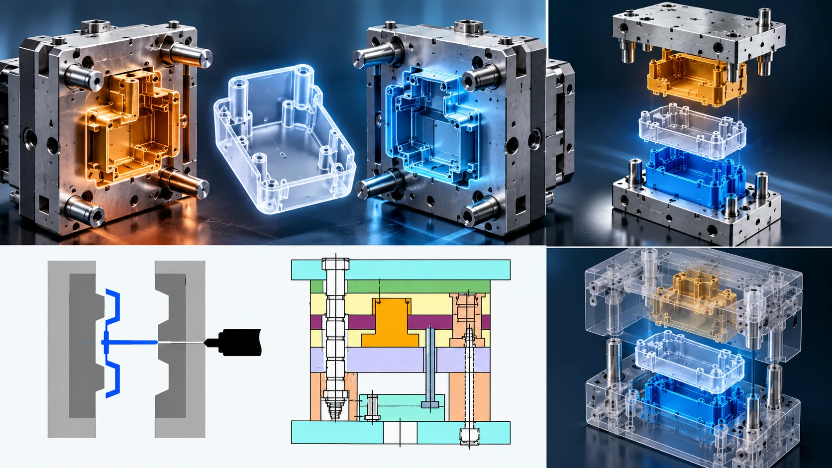
Core and Cavity refer primarily to the tooling geometry that forms the molded product, while the moldbase is the broader mechanical structure containing plates, guides, ejectors, fasteners, cooling components and other standardized tooling elements.
After Core/Cavity development, Creo Expert Moldbase can support detailed moldbase engineering and standard-component placement.
From Core and Cavity Design to CNC Machining
Core/Cavity splitting is only one stage of tooling development. Core Inserts, Cavity Inserts and other mold components must ultimately be manufactured using appropriate machining strategies.
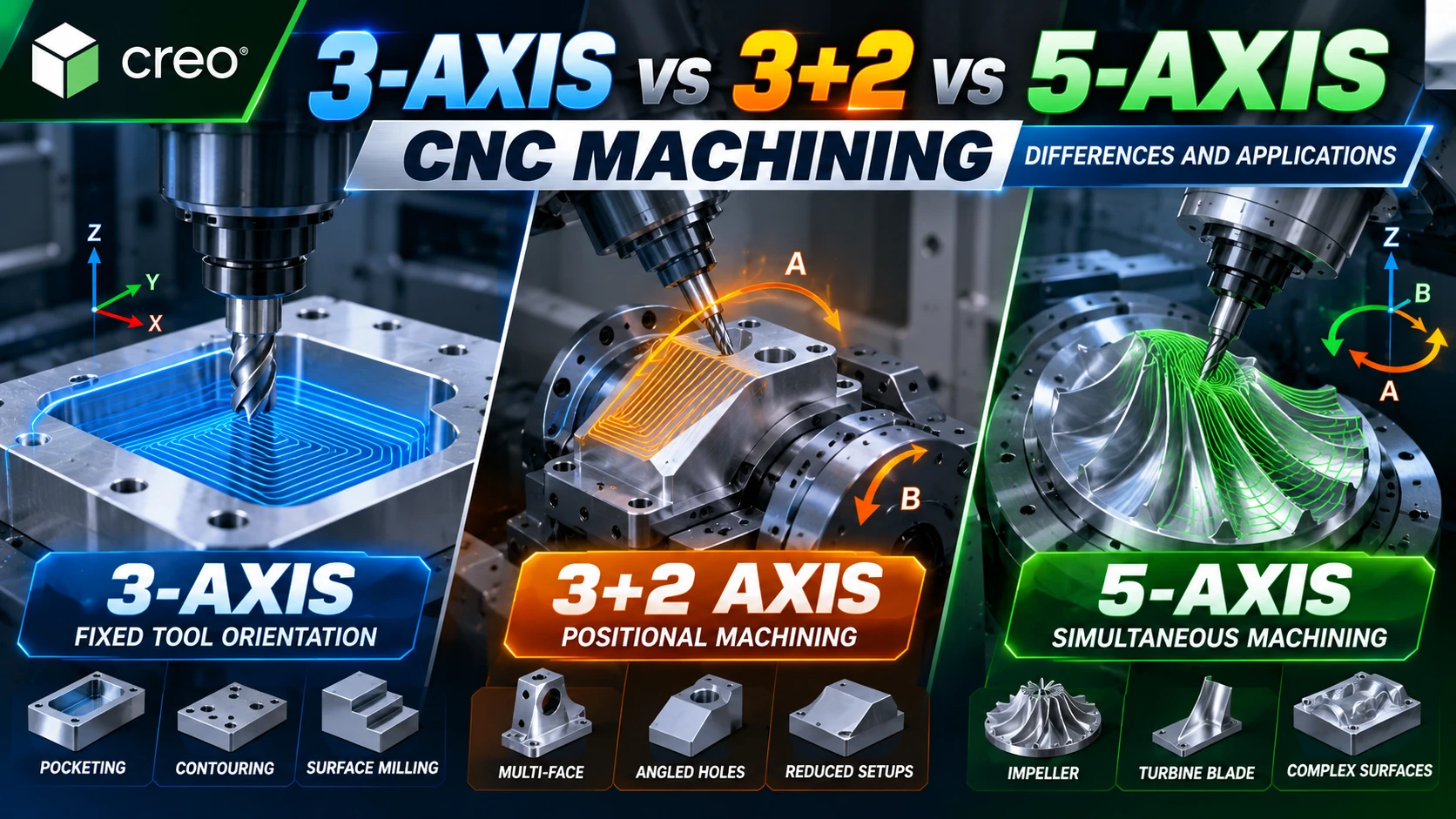
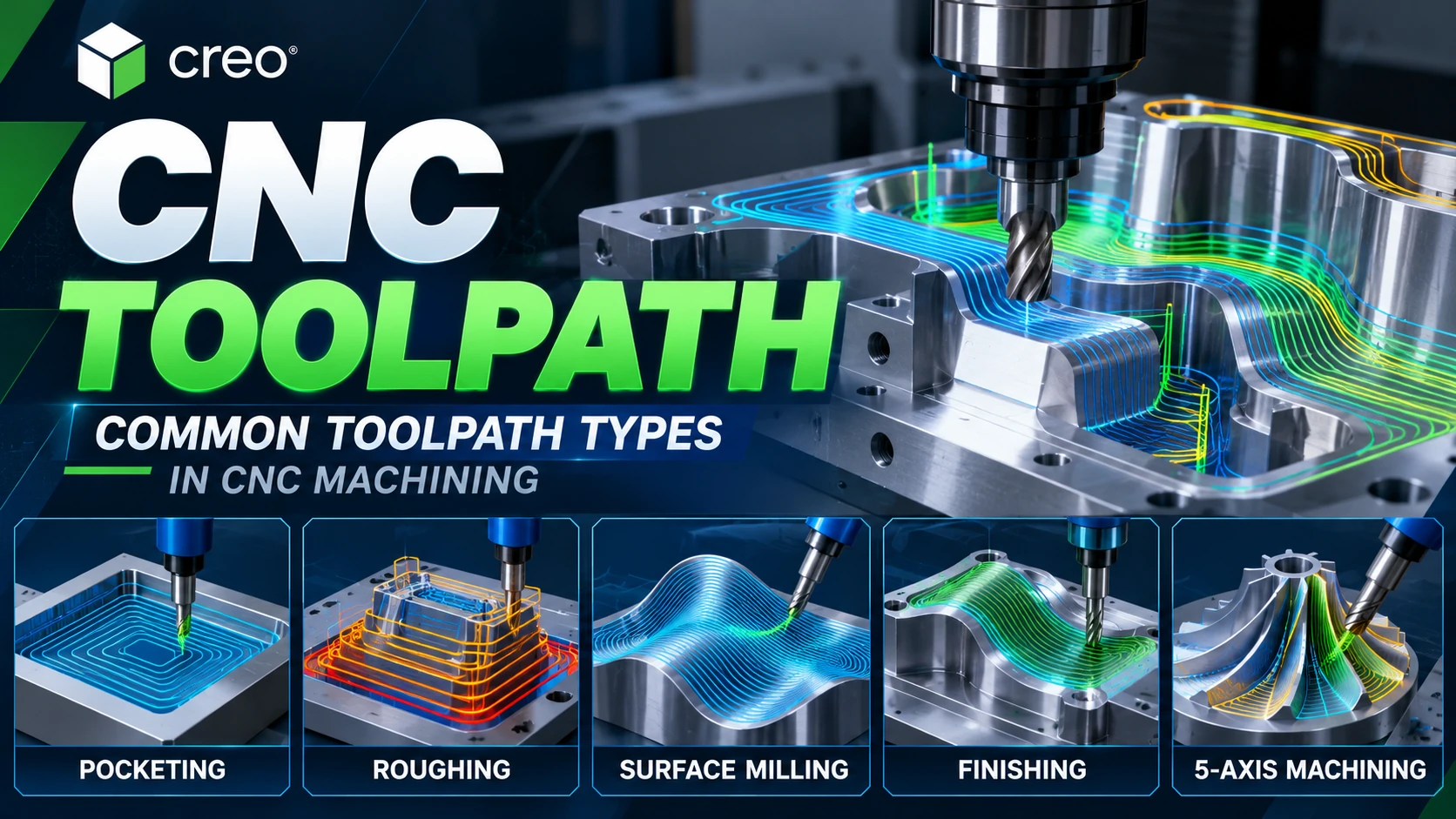
Roughing can remove bulk material, while rest machining and finishing address remaining material and final surface requirements. Deep cavities, angled walls and difficult cutter-access regions may require 3+2 or 5-axis machining depending on machine kinematics and tooling.
Explore Creo CAM for integrated CAD/CAM workflows and CNC Toolpath strategies for downstream mold manufacturing.
Common Core and Cavity Splitting Problems
Incorrect Pull Direction
An unsuitable pull direction can increase undercuts, complicate the Parting Line and require additional tooling mechanisms.
Insufficient Draft Analysis
Missing or unsuitable draft can create release problems and require product changes after tooling development has already begun.
Incomplete Parting Surface
Gaps, intersections or incomplete boundaries in a Parting Surface can prevent the tooling volume from splitting as intended.
Undetected Undercuts
Undercuts that are not identified early may make a basic Core/Cavity configuration impossible to open using the intended mold movement.
Ignoring Machinability
Geometry can be valid in CAD while remaining difficult to manufacture. Cutter access, tool length, electrode requirements, setup strategy and multi-axis machining should therefore be considered during mold design.
 Are Core and Cavity Always Only Two Components?
No. Core and Cavity describe the principal forming regions, but practical tooling can contain multiple inserts, sliders, side cores and other components. Multi-cavity molds can also contain several sets of product-forming geometry within a single moldbase.
FAQ About Core and Cavity
What are Core and Cavity?
Core and Cavity are the primary mold regions that combine to create the geometry of a molded product.
Is the Core always on the moving half of the mold?
No. The actual Core/Cavity arrangement depends on product geometry, ejection strategy, tooling architecture and the requirements of the specific mold.
What is the difference between a Parting Line and a Parting Surface?
The Parting Line represents the relevant boundary on the product geometry, while the Parting Surface is the surface geometry used to establish the boundary for separating mold volumes.
Why is Draft Analysis required before mold splitting?
Draft Analysis helps evaluate whether product surfaces can release along the intended Pull Direction and identifies regions that may create tooling challenges.
Can an undercut be handled using only Core and Cavity?
Not always. Some undercuts require sliders, lifters, side cores or inserts to release the product during mold opening.
Can PTC Creo split Core and Cavity?
Yes. Creo provides specialized mold-design tools for surface classification, Parting Surfaces, Mold Volumes and Volume Split operations used to develop Core/Cavity geometry.
What is Creo Tool Design Extension?
Creo Tool Design Extension supports mold and casting tooling development, including parting geometry, associative Core/Cavity splitting, sliders, inserts and related tooling deliverables.
Can Core and Cavity geometry be machined using Creo CAM?
Yes. Tooling geometry developed in Creo can continue into Creo CAM workflows for CNC toolpath programming and manufacturing.
Explore PTC Creo Mold Solutions
An integrated workflow from Product Model → Draft Analysis → Parting Surface → Core/Cavity → Moldbase → CAM can help mold manufacturers maintain more consistent engineering data between product design, tooling development and manufacturing.
CADCAM SOFTWARE supports manufacturers in evaluating PTC Creo solutions according to mold complexity, engineering workflow, number of users and downstream CAD/CAM requirements.
For technical details, see the PTC Core/Cavity Volume Split example and Creo Tool Design Extension.