What Is a Toolpath? 10 Common CNC Toolpath Types
What is a Toolpath? A toolpath is the defined path followed by a cutting tool during a CNC machining operation. It determines where the cutter moves, how it approaches the workpiece, where material is removed and how the tool exits or transitions between machining regions.
In CAM programming, selecting an appropriate CNC toolpath can directly affect material removal, machining time, cutter accessibility, cutting conditions and surface quality. The same component can therefore be machined using significantly different strategies depending on the selected toolpath.
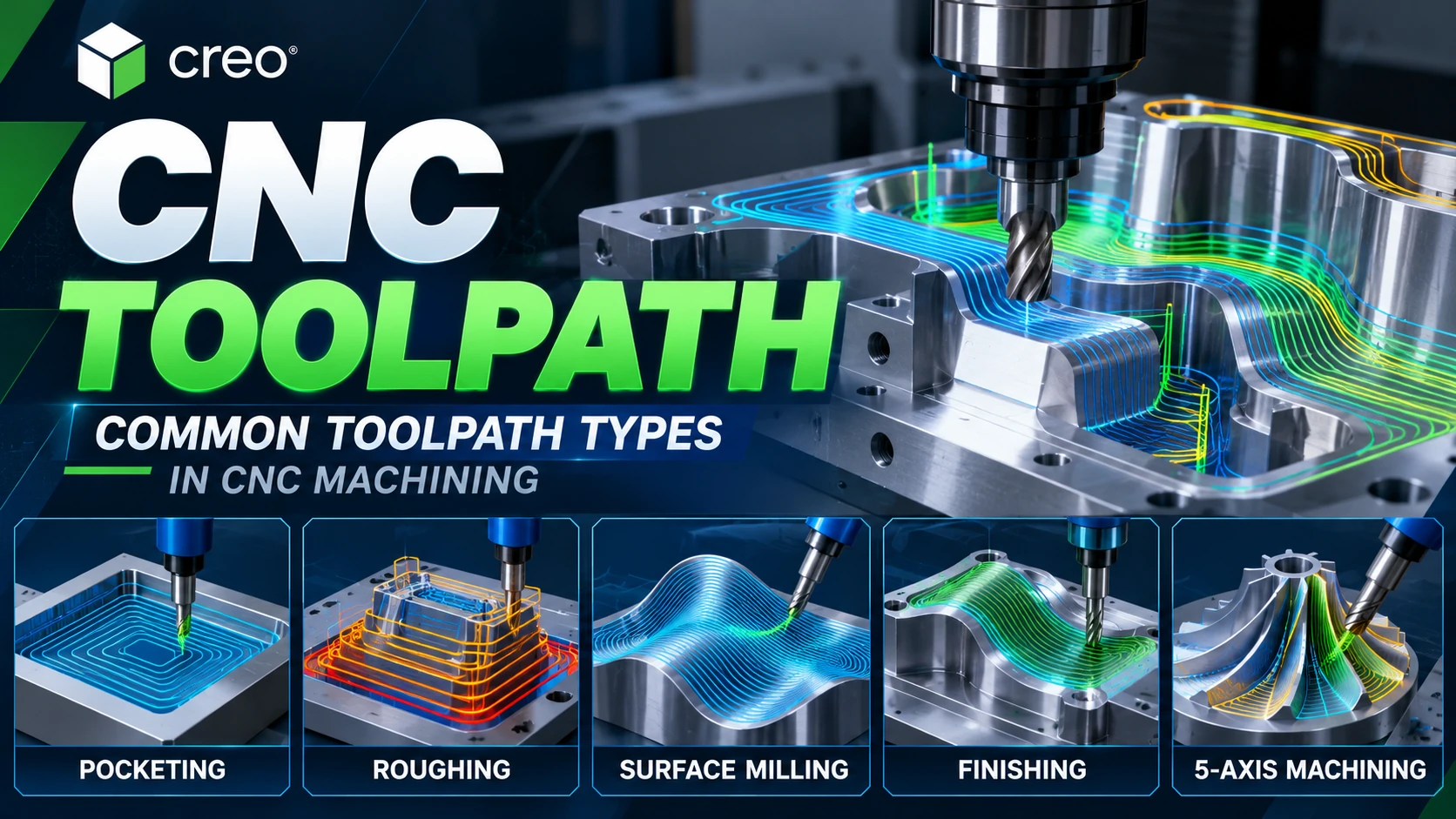
Depending on part geometry, CNC machine configuration and machining objectives, programmers can use strategies including Face Milling, Roughing, Pocketing, Profile Milling, Volume Milling, Surface Milling, Finishing, Trajectory Milling and Multi-Axis Toolpaths.
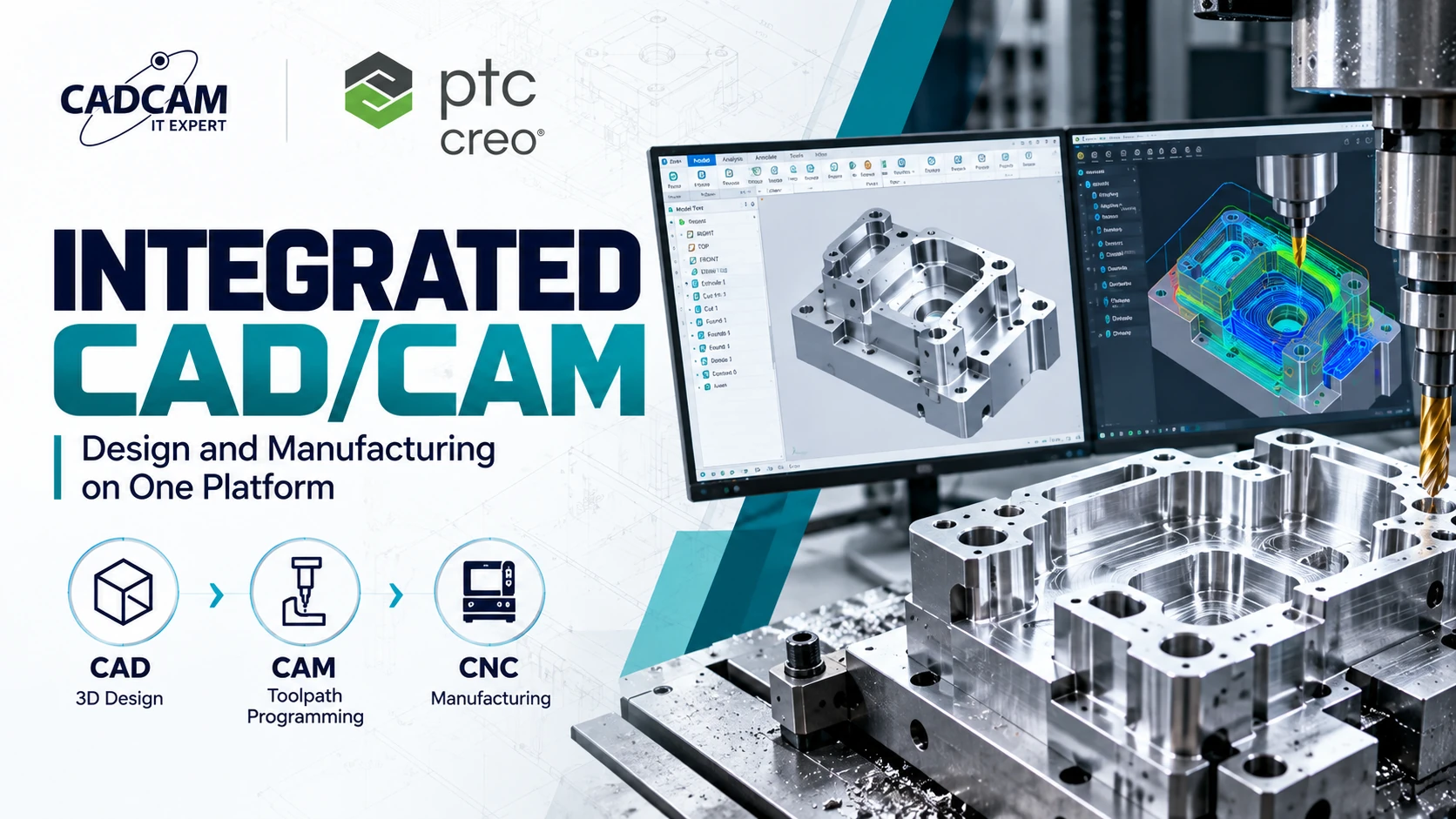
PTC Creo CAM provides an integrated environment for creating CNC toolpaths from CAD geometry, simulating machining operations and generating machine-specific NC programs through post processing.
What Is a Toolpath in CNC Machining?
A toolpath can be understood as the path followed by the control point of a cutting tool during a machining operation. A complete toolpath can include cutting motion as well as approach, entry, exit, retract, linking and positioning moves.
The CAM system calculates these movements according to part geometry, stock, CNC machine configuration, cutting tools, holders, machining regions and manufacturing parameters.
- Cutting Moves: motion while material is being removed.
- Approach: motion toward the machining region.
- Entry: motion used to enter the material.
- Exit: motion used to leave the cutting region.
- Retract: movement away from the workpiece.
- Linking Moves: transitions between machining regions.
- Rapid Moves: non-cutting positioning motion.
Where Does a Toolpath Fit into the CAD/CAM/CNC Workflow?
A simplified manufacturing workflow can be represented as: CAD Model → CAM Setup → Machining Strategy → Toolpath → Simulation → Post Processor → NC/G-code → CNC Machine.
1. CAD Model
The workflow begins with the geometry of the component to be manufactured. The model can be created directly in Creo or prepared from suitable external CAD data.
2. CAM Setup
The CAM programmer defines the workpiece, fixtures, machining coordinate system, CNC machine, cutting tool, holder and other manufacturing conditions.
3. Select a Machining Strategy
A suitable strategy such as Face Milling, Roughing, Pocketing, Surface Milling or Finishing is selected according to the geometry and machining objective.
4. Generate the Toolpath
The CAM system calculates cutter movement using the selected geometry, tool and manufacturing parameters.
5. Simulation and Verification
The calculated toolpath can be reviewed before machining to evaluate cutter movement, material removal and potential machining problems according to the simulation capabilities being used.
6. Post Processing
A Post Processor converts CAM data into an NC program appropriate for the target CNC machine and controller.
Are Toolpaths and G-code the Same?
No. A toolpath and G-code are related, but they are not the same thing. A toolpath represents machining motion defined in the CAM environment, while an NC/G-code program contains machine-control instructions generated through post processing.
The relationship can be represented as: Machining Strategy → Toolpath → Post Processor → NC/G-code → CNC Machine.
10 Common CNC Toolpath Types
Toolpath terminology varies between CAM systems. Creo NC provides a range of Milling NC Sequences for different machining objectives, including Face Milling, Volume Milling, Roughing, Re-Roughing, Local Milling, Surface Milling and other specialized strategies.
1. Face Milling Toolpath
Face Milling is used to machine the face of a workpiece. It is commonly used to create a flat reference surface, remove initial stock or prepare a component for subsequent machining operations.
2. Roughing Toolpath
Roughing focuses on removing a relatively large amount of material during an early machining stage. In Creo NC, Roughing includes high-speed milling sequences designed to remove material inside a defined Mill Window boundary.
Important considerations include Stepdown, Stepover, Stock Allowance, Feed Rate, Spindle Speed, cutter entry and cutting load.
3. Pocket Toolpath
Pocketing removes material from a defined pocket region and is commonly used for mechanical pockets, housings, recesses, slots and prismatic components.
4. Profile / Contour Toolpath
Profile or Contour Toolpaths are used when the cutter needs to follow a defined part profile. Creo Profile Milling can support vertical or slanted surfaces and multi-axis workflows depending on the machining configuration.
5. Volume Milling Toolpath
Volume Milling in Creo NC is a 2.5-axis slice-by-slice milling method used to remove material from a specified milling volume. It is useful for prismatic components and machining regions where the stock to be removed can be clearly defined.
6. Surface Milling Toolpath
Surface Milling is used to machine horizontal or slanted 3D surfaces. Creo provides multiple methods for defining Surface Milling cuts, allowing the calculated toolpath to change according to the selected method, parameters and geometric references.
Surface Milling is particularly important for freeform surfaces, mold cores and cavities, and other complex 3D geometry. Mold manufacturers can also explore Creo Mold Design for upstream tooling development.
7. Finishing Toolpath
Finishing is performed after roughing and intermediate operations to machine detailed geometry toward its final required condition. At this stage, the focus generally shifts from bulk material removal to geometry control and surface quality.
8. Re-Roughing / Rest Machining / Local Milling
Material can remain in small corners, deep regions or geometry that a larger roughing cutter could not reach. Re-Roughing and Local Milling strategies can target these remaining regions, often with a smaller cutting tool.
9. Trajectory Milling Toolpath
Trajectory Milling provides direct control over cutter movement along defined geometry. Creo supports Tool Motions for 3-, 4- and 5-axis Trajectory Milling sequences, including Curve Cut, Drive Surface Cut, Follow Curve and multiple approach, exit and retract motions.
10. Multi-Axis / 5-Axis Toolpath
For complex geometry, X, Y and Z translation alone may not provide sufficient cutter access. Multi-Axis Toolpaths add control over cutter or workpiece orientation depending on the machine configuration and machining strategy.
Typical applications include impellers, turbine blades, aerospace components, undercuts, complex molds and geometry that is difficult to access using conventional 3-axis machining.
Other CNC Toolpath Types in Creo NC
The official PTC Creo Milling NC Sequences documentation provides additional information about Creo manufacturing strategies and specialized NC sequences.
- Corner Finishing.
- Swarf Milling.
- Engraving.
- Thread Milling.
- Drilling.
- Auto Drilling.
Roughing vs. Finishing Toolpaths
| Factor | Roughing | Finishing |
|---|---|---|
| Main Objective | Bulk material removal | Final geometry and surface |
| Material Removal | Generally higher | Generally lower |
| Stock Allowance | Normally leaves stock | Approaches final dimensions |
| Priority | Material-removal efficiency | Geometry and surface quality |
| Process Stage | Early/intermediate | Later |
Important CNC Toolpath Parameters
Stepover
Stepover defines the lateral distance between adjacent cutting passes and can affect the number of passes, material engagement and resulting surface condition.
Stepdown
Stepdown defines the depth difference between successive machining levels and should be selected according to the tool, workpiece material, machine and machining strategy.
Feed Rate
Feed Rate defines cutter feed during machining and should be selected according to the cutting tool, material, spindle conditions and machine capability.
Spindle Speed
Spindle Speed defines rotational speed and is an important parameter when establishing appropriate cutting conditions.
Stock Allowance
Stock Allowance is material intentionally left after one machining operation for removal during a later operation.
Entry, Exit and Linking
Approach, entry, exit, retract and linking strategies determine how the cutter transitions between machining regions and can influence total cycle time and machining conditions.
Why Is CNC Toolpath Optimization Important?
A toolpath that can be successfully calculated by CAM is not necessarily the most appropriate toolpath for actual production. CAM programmers must also consider machine capability, cutting tools, holders, fixtures, workpiece material, rigidity and production objectives.
Toolpath evaluation can therefore include Toolpath Length, Cycle Time, Non-Cutting Motion, Feed and Spindle conditions, Cutting Load, Cutter Accessibility, Remaining Stock, Collision Risk and Surface Quality.
Toolpaths in PTC Creo CAM
PTC Creo CAM integrates NC programming capabilities with Creo design geometry. Manufacturing operations and toolpaths can remain associated with CAD geometry rather than relying entirely on geometry translation between independent CAD and CAM systems.
PTC Creo Production Machining provides NC programming capabilities for 3-axis milling, turning and Wire EDM together with CAD/CAM associative updates, post-processing, material-removal simulation and related manufacturing capabilities. Explore the official PTC Creo Production Machining Extension for additional product information.
For an overview of the integrated manufacturing workflow, see PTC Creo CAM for CNC programming and machining.
Basic Toolpath Workflow in Creo CAM
- Prepare the CAD Model: create or receive the part geometry.
- Set Up Manufacturing: define the workcell, stock, fixtures and coordinate system.
- Select the Cutting Tool: configure the cutter and holder.
- Select an NC Sequence: choose the appropriate machining strategy.
- Define Parameters: configure Feed, Spindle, Stepdown, Stepover and related parameters.
- Generate the Toolpath: calculate cutter movement.
- Simulate and Verify: review cutter motion and material removal.
- Post Process: generate the NC program for the target machine and controller.
FAQ About CNC Toolpaths
What is a Toolpath?
A toolpath is the defined path followed by a cutting tool during CNC machining. It is calculated in CAM according to geometry, cutting tools, machine configuration and machining parameters.
Are a toolpath and G-code the same?
No. A toolpath represents machining motion in CAM, while an NC/G-code program contains machine instructions generated through post processing.
What are the most common CNC toolpath types?
Common categories include Face Milling, Roughing, Pocketing, Profile/Contour, Volume Milling, Surface Milling, Finishing, Rest Machining, Trajectory Milling and Multi-Axis Toolpaths.
What is a Roughing Toolpath?
A Roughing Toolpath is designed to remove bulk material during an early machining stage while normally leaving appropriate stock for subsequent operations.
What is a Finishing Toolpath?
A Finishing Toolpath is used during a later machining stage to machine detailed geometry toward its required final shape and surface condition.
What is Rest Machining?
Rest Machining targets material that remains after previous machining operations, particularly in small corners, deep areas or regions that a larger cutter could not reach.
What is a 5-axis Toolpath?
A 5-axis Toolpath uses multi-axis machine capability to control cutter position and orientation while machining complex geometry.
Can PTC Creo generate CNC toolpaths?
Yes. Creo Manufacturing and CAM solutions provide NC programming capabilities and machining strategies for milling, turning and multi-axis workflows depending on the deployed configuration.
Can Creo toolpaths update when CAD geometry changes?
Creo supports associative CAD/CAM workflows. When design geometry changes, affected manufacturing operations and toolpaths can be updated or regenerated to reflect appropriate design modifications.
Discuss CNC Programming with CADCAM SOFTWARE
CADCAM SOFTWARE is a PTC Gold Partner in Vietnam, supporting manufacturers with PTC solutions for product design, mold development and CNC programming.
CADCAM SOFTWARE COMPANY LIMITED
Hanoi Office: No. 25, Alley 34, Giap Nhat Street, Thanh Xuan Ward, Hanoi, Vietnam
Ho Chi Minh City Office: R.1508, Tower A, Masteri Centre Point, N2 Street, Long Binh Ward, Ho Chi Minh City, Vietnam
Tel: 024 6673 7986
Hotline: 0907 658 000
Email: info@cadcamsoftware.vn
Website: https://cadcamsoftware.vn/en/