Creo Mold Design: Complete Mold Design Workflow in PTC Creo
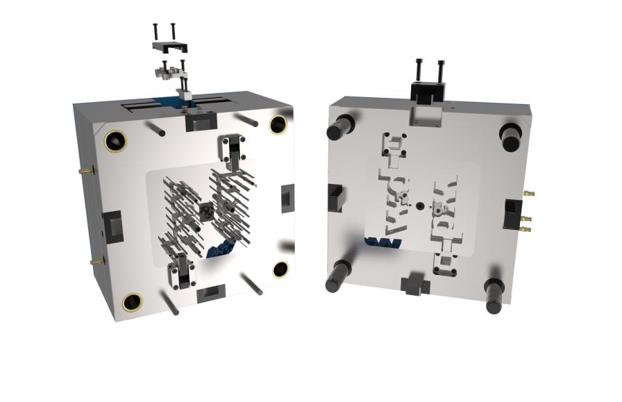
Creo Mold Design is a mold development workflow within the PTC Creo ecosystem that enables engineers to create tooling directly from 3D CAD product models. The process can include draft analysis, pull direction definition, parting line creation, parting surface development, core and cavity splitting, moldbase design, mold analysis, and manufacturing preparation.
Instead of developing product data and mold tooling in separate systems, Creo allows engineering teams to build an associative workflow between Product Design and Tooling. This becomes particularly valuable when product geometry changes repeatedly throughout the development process.
Companies looking to establish an integrated mold design and manufacturing workflow can explore Creo Mold software solutions provided by CADCAM Software for Mold & Die applications.
What Is Creo Mold Design?
Creo Mold Design refers to the collection of tools and workflows used to develop mold tooling within the PTC Creo environment. Engineers can use the original 3D product model as the foundation for developing the tooling components required for manufacturing.
Typical mold design activities include:
- Product geometry inspection.
- Pull Direction definition.
- Draft and Undercut analysis.
- Parting Line creation.
- Parting Surface development.
- Core and Cavity splitting.
- Slider and Insert design.
- Moldbase development.
- Runner, Gate, and Waterline layout.
- Tooling data preparation for manufacturing.
Dedicated solutions such as Creo Tool Design Extension and Creo Expert Moldbase Extension expand the tooling capabilities available within the Creo environment.
Why Should Mold Design Be Directly Connected to CAD Data?
In real engineering projects, a product model rarely remains unchanged from the beginning to the end of development. Customers or R&D teams may modify dimensions, Draft Angles, Ribs, Bosses, Holes, Wall Thickness, surfaces, or other product features.
If Product Design and Mold Design are developed in separate systems, every Engineering Change may require engineers to manually inspect and update multiple tooling components.
Creo’s associative workflow helps maintain relationships between product geometry and tooling data. When the product geometry changes, engineering teams can better evaluate how those changes affect the mold design.
This is one of the key advantages of developing CAD and Mold Design workflows on a common platform.
Mold Design Workflow in PTC Creo
A typical mold design workflow in Creo can be organized into the following stages.
Step 1: Prepare the 3D Product Model
The mold design process begins with the 3D product model. The model can be created directly in Creo or imported from another CAD system for further tooling development.
At this stage, engineers should evaluate important design conditions such as:
- Product geometry.
- Wall Thickness.
- Draft Angle.
- Undercuts.
- Complex surfaces.
- Product release direction.
- Areas that may create injection molding challenges.
For companies that want to develop product geometry and tooling within the same environment, Creo CAD can provide the 3D design foundation before moving into the Mold Design process.
Step 2: Define Pull Direction and Analyze Draft
Pull Direction defines the direction in which the molded product is removed from the tool. It is one of the most important design parameters to establish before developing the Parting Line, Parting Surface, Core, Cavity, Slider, and other tooling components.
After defining the Pull Direction, engineers should evaluate Draft Angles and identify potential Undercut regions.
Detecting geometry problems early can reduce the risk of extensive tooling modifications later in the project when Moldbase or Manufacturing activities have already started.
Step 3: Create the Parting Line
Parting Line defines the separation boundary of the mold and plays an important role in determining Core and Cavity geometry.
For simple products, the Parting Line may be relatively straightforward. However, products containing complex surfaces, Ribs, Bosses, Undercuts, asymmetric geometry, or demanding cosmetic requirements often require more careful control of the Parting Geometry.
Defining an appropriate Parting Line early in the process makes the subsequent Parting Surface development more manageable.
Step 4: Build the Parting Surface
Parting Surface is the surface geometry used to separate different mold regions and is a critical element of the Core/Cavity splitting process.
The Parting Surface should be developed according to the product geometry, Pull Direction, and mold structure.
An unsuitable Parting Surface can create difficulties during Core/Cavity Splitting, mold opening, machining, or future engineering changes.
Step 5: Split the Core and Cavity
After the Parting Geometry has been completed, engineers can divide the tooling model into Core and Cavity components.
The Core typically forms the internal surfaces of the molded product, while the Cavity generally forms the external product surfaces.
Products with Undercuts or more complex geometry may also require Sliders, Inserts, Lifters, or other mechanisms to support part release.
A simplified workflow can be represented as:
Product Design → Pull Direction → Parting Geometry → Core/Cavity → Tooling
How Does Creo Tool Design Extension Support Mold Design?
Creo Tool Design Extension provides specialized capabilities for developing mold and casting tooling directly within the Creo environment.
Key capabilities can include Parting Line and Parting Surface creation, associative Core/Cavity Splitting, Slider and Insert development, and manufacturing deliverables.
Because tooling is developed from the product design data, engineering teams can create a connected workflow from product development through manufacturing instead of repeatedly exporting and importing geometry between separate systems.
Creo EMX for Automated Moldbase Design
After Core and Cavity development is completed, the next stage is building the Moldbase.
A Moldbase may contain components such as:
- Mold Plates.
- Guide Components.
- Ejector Pins.
- Screws.
- Cooling Components.
- Runner Components.
- Other standard tooling components.
Creo Expert Moldbase Extension (EMX) helps automate many repetitive tasks associated with Moldbase development and standard component placement.
EMX can be particularly useful for companies that design many molds, frequently work with standardized Moldbases, use large libraries of standard components, or want to reduce repetitive manual modeling tasks.
Runner, Gate, and Cooling System Design
A complete mold includes much more than the Core, Cavity, and Moldbase. Engineers must also develop various components required for the injection molding process.
Common tooling elements include:
- Sprue.
- Runner.
- Gate.
- Cooling Waterlines.
- Ejector System.
Developing these components within the same design environment creates a more consistent workflow between Product Design and Tooling.
Creo Mold Analysis in the Mold Development Workflow
Before investing in physical mold manufacturing, companies should evaluate product manufacturability and identify potential risks that may occur during the injection molding process.
Creo Mold Analysis enables engineers to analyze injection molding behavior directly from the design model.
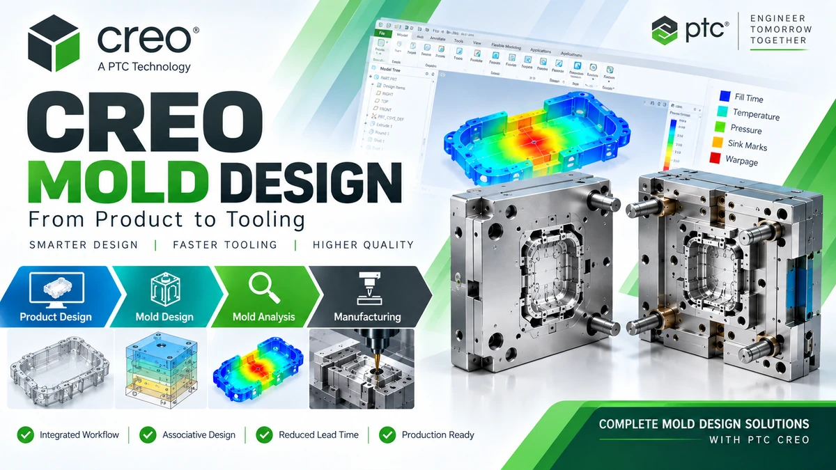
Engineering teams can evaluate conditions such as Fill Behavior, Short Shot, Weld Lines, Air Traps, Sink Marks, Shrinkage, and Temperature Distribution.
Analysis results provide additional engineering data that can help teams modify the product or tooling before significant manufacturing costs are incurred.
Which Companies Can Benefit from Creo Mold Design?
Plastic Injection Mold Manufacturers
Companies specializing in Injection Mold development can use Creo to establish a workflow from product geometry through Parting Surface development, Core/Cavity splitting, and Moldbase design.
Automotive and Motorcycle Component Suppliers
Automotive suppliers frequently manage multiple Engineering Changes during product development.
An associative workflow between Product Design and Tooling helps engineering teams better control geometry changes and their impact on mold development.
Electronics Manufacturers
Products such as Plastic Housings, Connectors, electronic enclosures, and precision molded components often contain complex geometry and demanding surface requirements.
Creo Mold Design can support companies developing tooling workflows for these types of products.
Mold & Die Manufacturers
Companies specializing in mold and tooling development can combine Creo Tool Design and Creo EMX to standardize the process from Parting Geometry through Moldbase development.
From Creo Mold Design to CNC Manufacturing
After the mold design has been completed, the Core, Cavity, Inserts, and other tooling components must move into the Manufacturing stage.
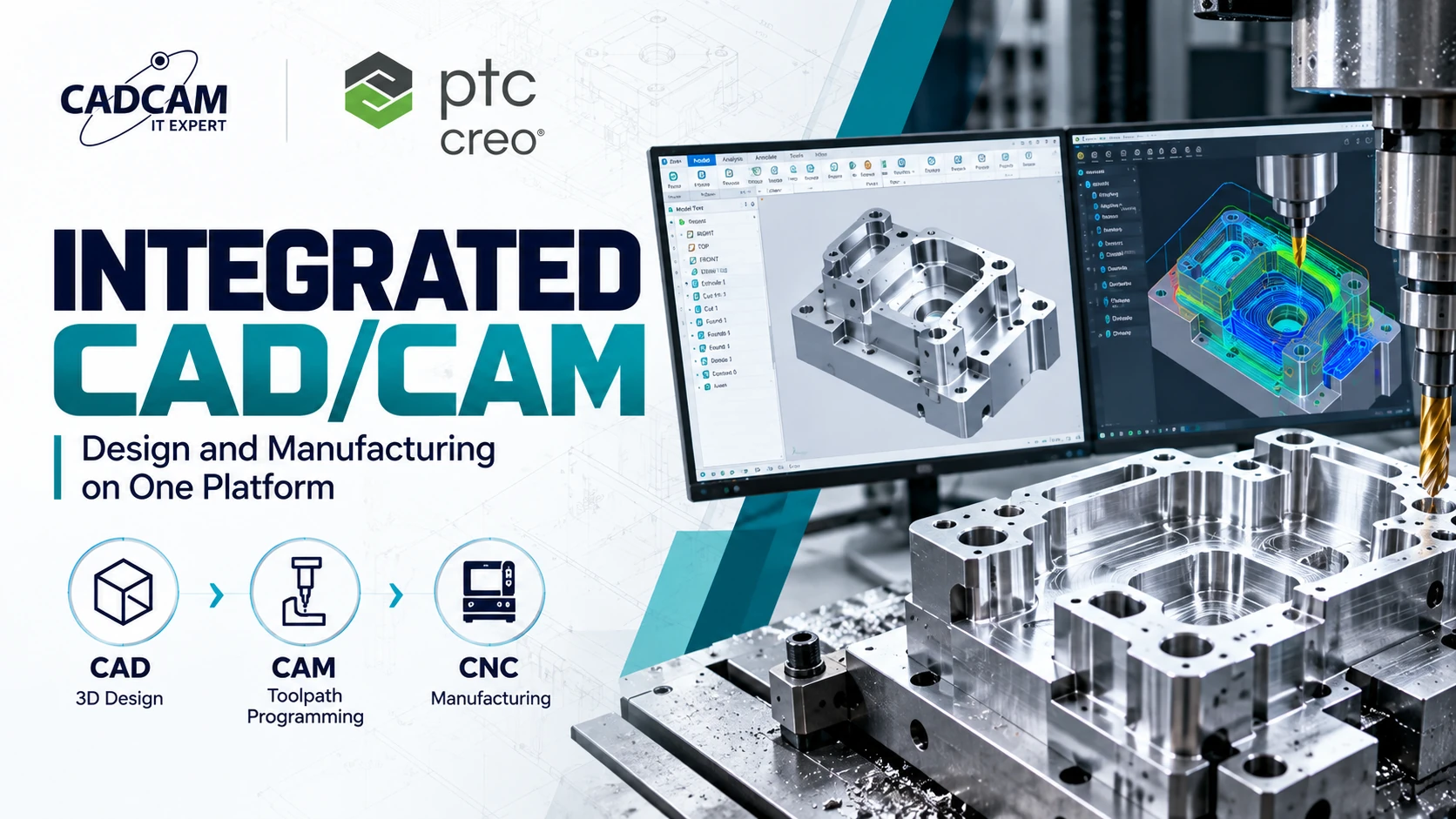
Within the Creo ecosystem, companies can continue with Creo CAM to develop CNC machining processes directly from Creo design data.
The workflow can therefore be expanded into:
Creo CAD → Creo Mold Design → Creo CAM → CNC Manufacturing
Using the original CAD model throughout the workflow helps reduce intermediate geometry conversion and supports associativity when product geometry changes.
Benefits of Implementing Creo Mold Design
The value of Creo Mold Design extends beyond simply creating Core and Cavity geometry. A major benefit is the ability to develop a connected mold design and manufacturing workflow.
- Develop tooling directly from 3D CAD data.
- Evaluate Draft and geometry before mold development.
- Create Parting Lines and Parting Surfaces.
- Develop Core, Cavity, Slider, and Insert geometry.
- Automate Moldbase design activities with Creo EMX.
- Evaluate injection molding behavior before manufacturing the physical mold.
- Connect mold design data with CNC machining workflows.
- Reduce dependence on CAD/CAM geometry conversion between different systems.
Conclusion
Creo Mold Design provides an integrated workflow for developing molds from the original product model through tooling and manufacturing.
The overall process can be represented as:
Product Design → Draft & Pull Direction → Parting Line → Parting Surface → Core/Cavity → Moldbase → Mold Analysis → Manufacturing
For mold manufacturers, one of the most important benefits of Creo is the ability to maintain relationships between Product Design and Tooling, especially when product geometry changes throughout the development cycle.
Creo Mold Solutions for Manufacturing Companies
CADCAM Software supports companies in evaluating and selecting Creo configurations based on actual mold design workflows, product complexity, automation requirements, and manufacturing processes.
A Creo Mold solution can combine Creo CAD, Creo Tool Design Extension, Creo Expert Moldbase Extension, Creo Mold Analysis, and Creo CAM depending on the engineering requirements of each company.
Explore Creo Mold solutions and contact CADCAM Software for consultation →