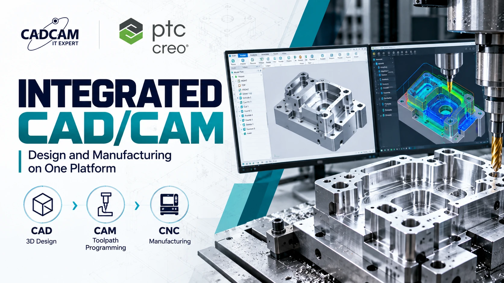
What Is Integrated CAD/CAM? Benefits of Design and Manufacturing on One Platform
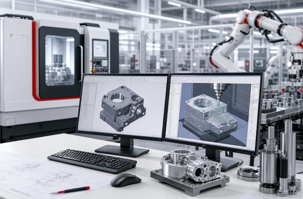
What Is Integrated CAD/CAM? Integrated CAD/CAM is an approach that connects computer-aided design (CAD) with computer-aided manufacturing (CAM) through a shared software environment or an associative data workflow. Instead of repeatedly exporting and importing product geometry between disconnected systems, engineers can use design models to prepare machining operations, generate toolpaths, simulate material removal and produce NC programs for CNC machines.
The main advantage is not simply having CAD and CAM tools available in one interface. It is maintaining a reliable relationship between engineering geometry and manufacturing data. When the design changes, associated manufacturing operations can be reviewed, updated and regenerated as needed before releasing a revised NC program. This connection helps design and manufacturing teams work from more consistent technical information.
What Is Integrated CAD/CAM in Manufacturing?
Integrated CAD/CAM connects product geometry and manufacturing operations so engineers can prepare CNC machining directly from design data. Depending on the platform, integration may range from controlled data exchange to native, associative relationships between CAD models and CAM features.
CAD tools define product geometry, design features, assemblies and engineering drawings. CAM tools use the relevant geometry to establish stock, machining setups, cutting tools, machining strategies and toolpaths. A post processor then converts validated toolpath data into NC instructions appropriate for the target machine and controller.
For manufacturers producing precision components, molds, dies and industrial equipment, this connected approach can support better coordination between design revisions and machining preparation.
CAD vs CAM: What Is the Difference?
| Factor | CAD | CAM |
|---|---|---|
| Purpose | Product design and engineering | Machining preparation and programming |
| Core Data | 2D/3D geometry, features and assemblies | Stock, tools, operations and toolpaths |
| Typical Users | Design engineers and R&D teams | Manufacturing engineers and CNC programmers |
| Outputs | 3D models and engineering drawings | Toolpaths, simulations and NC programs |
| Primary Question | What needs to be manufactured? | How will it be manufactured? |
CAD and CAM perform different functions. CAD defines product geometry and design intent, while CAM translates machining requirements into tool movements and manufacturing instructions.
Integrating the two helps reduce unnecessary handoffs and supports a more consistent design-to-manufacturing process.
How Does an Integrated CAD/CAM Workflow Work?
1. Create the 3D CAD Model
The design engineer develops a parametric product model with dimensions, geometric constraints, holes, pockets, surfaces and other features. This model becomes the reference for downstream manufacturing preparation.
2. Prepare the Manufacturing Setup
The CAM programmer defines the manufacturing model, stock geometry, coordinate system, fixtures, cutting tools and machine setup. Work offsets and setup orientation must correspond to actual shop-floor conditions.
3. Generate Machining Operations and Toolpaths
The engineer selects suitable operations such as facing, pocket milling, roughing, finishing and drilling. More advanced applications may require indexed or simultaneous multi-axis machining, depending on the equipment and software configuration.
4. Simulate and Verify Machining
Before releasing a program, the programmer reviews material removal, remaining stock and potential interference within the capabilities of the available simulation tools. Shop-floor validation and machine-specific safety checks remain essential.
5. Post-Process the Toolpaths
A configured post processor converts toolpath information into machine-specific NC code. The resulting program must be checked for coordinates, movements, tool commands and controller compatibility before machining.
6. Manage Engineering Changes
When CAD geometry changes, associated CAM references can reflect those changes. The programmer identifies affected operations, regenerates toolpaths where required, reruns verification and releases an approved NC program revision.
7 Benefits of Integrated CAD/CAM for Manufacturers
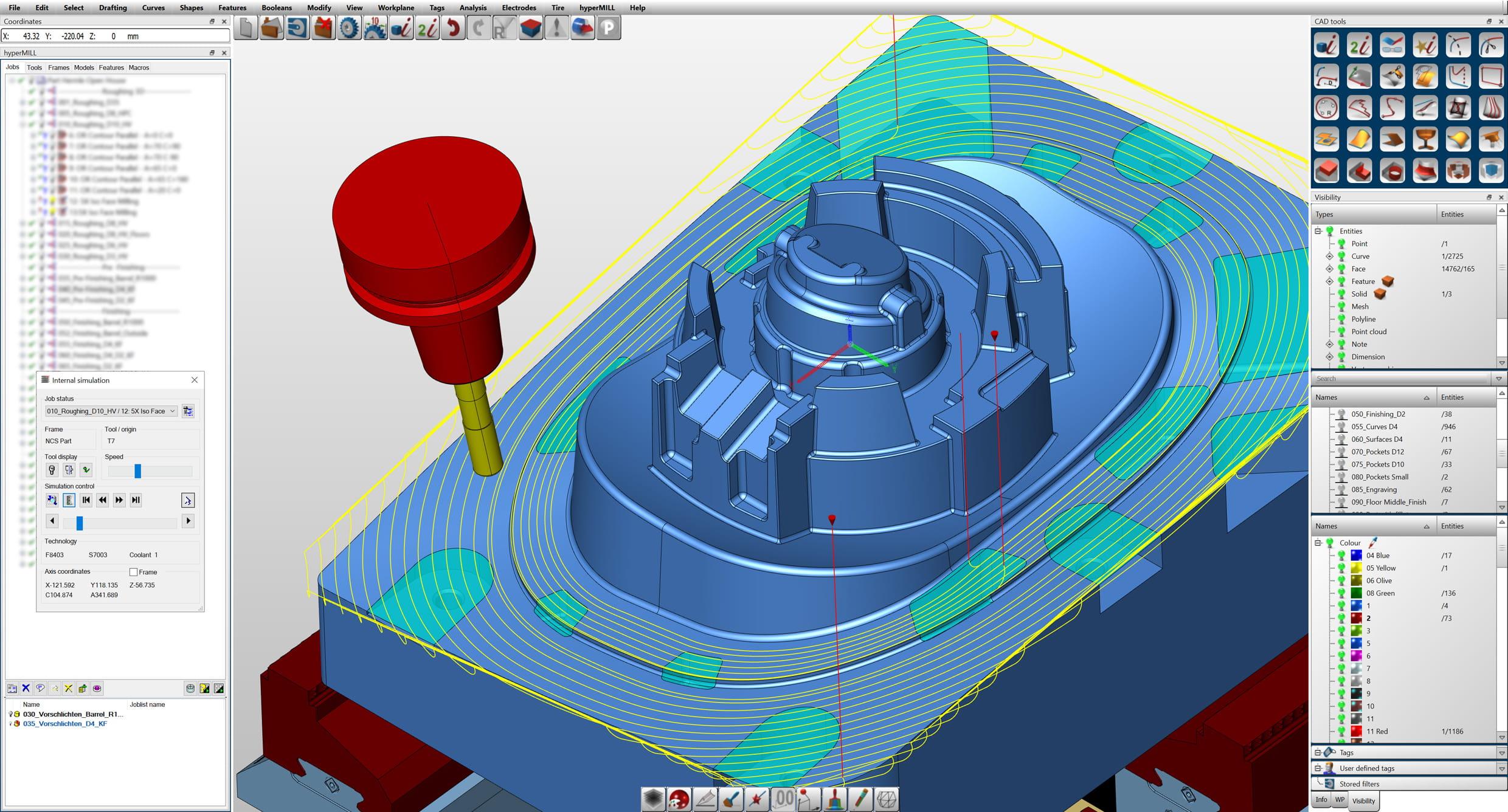 1. Reduce CAD-to-CAM Translation Issues
Working from native or directly associated design geometry can reduce dependence on intermediate formats such as STEP and IGES. This helps limit certain translation issues, including missing surfaces, geometry differences and loss of parametric relationships.
2. Support Associative Toolpath Updates
In an associative environment, machining references can respond to changes in the CAD model. However, updated toolpaths must still be regenerated and validated when geometry or manufacturing conditions change.
3. Improve Design and Manufacturing Consistency
Connected data can reduce the risk of programming from an outdated model when the organization also maintains appropriate revision control and engineering approval procedures.
4. Reduce Repetitive CNC Programming Work
Manufacturing teams may reuse existing operations, tooling information and proven machining strategies rather than rebuilding every setup from scratch. The actual benefit depends on part complexity and process standardization.
5. Identify Manufacturing Challenges Earlier
Access to design geometry and machining tools within a connected workflow can help engineers identify difficult tool access, deep cavities, small corner radii and complex fixture requirements earlier.
6. Strengthen Engineering Collaboration
Designers, manufacturing engineers and CNC programmers can coordinate changes using more consistent model and process information, especially when several teams contribute to the same product.
7. Support Digital Manufacturing Initiatives
Integrated CAD/CAM provides a foundation for connecting product design with manufacturing preparation. Combined with suitable product data management and change-control processes, it can improve traceability across engineering workflows.
Integrated CAD/CAM vs Separate CAD and CAM Systems
| Factor | Integrated CAD/CAM | Separate CAD and CAM |
|---|---|---|
| Geometry Transfer | May use directly associated native models | Often relies on file exchange or external interfaces |
| Engineering Changes | Supports associative updates where available | Depends on integration and data-management methods |
| Revision Control | Can support a more connected workflow | Requires coordination across applications |
| Flexibility | Depends on the platform and extensions | Allows selection of specialized tools |
| Implementation | Requires workflow, training and licensing evaluation | Requires interoperability and data-exchange evaluation |
| Best Fit | Teams prioritizing connected design and machining | Teams with established specialist applications |
An integrated platform is not automatically the best choice for every organization. Manufacturers with highly specialized CAM requirements or mature multi-vendor workflows should compare functionality, transition costs and existing engineering expertise before changing systems.
How Does PTC Creo Support Integrated CAD/CAM?
PTC Creo combines parametric 3D design with manufacturing capabilities available through appropriate extensions and packages. This allows manufacturing engineers to develop machining operations from Creo design geometry while maintaining associative relationships where supported.
Creo Parametric for Product Design
Creo Parametric provides feature-based 3D modeling, dimensional control and engineering change capabilities. The design model can serve as the reference for downstream manufacturing operations.
Creo CAM for CNC Programming
Creo CAM provides manufacturing programming capabilities within the Creo ecosystem. Depending on the licensed configuration, manufacturers can prepare milling, turning, holemaking, wire EDM or multi-axis machining operations.
Associative CAD/CAM Relationships
Associated machining references can reflect changes in the source design geometry, helping programmers identify which operations need regeneration or additional verification.
NC Simulation and Post Processing
Relevant Creo machining solutions support material-removal simulation, machining verification and post-processing capabilities. Exact functions depend on the extension, machine configuration and licensing.
Manufacturers can review the official Creo Production Machining Extension and Creo Machining Suite to understand available options.
Are your design and CNC programming teams working with disconnected software?
CADCAM SOFTWARE can help your organization review its design-to-manufacturing workflow, machining requirements and suitable PTC Creo configurations before selecting a solution.
Contact: +84 907 858 000 | info@cadcamsoftware.vn
Engineering Example: Integrated CAD/CAM for Mold Manufacturing
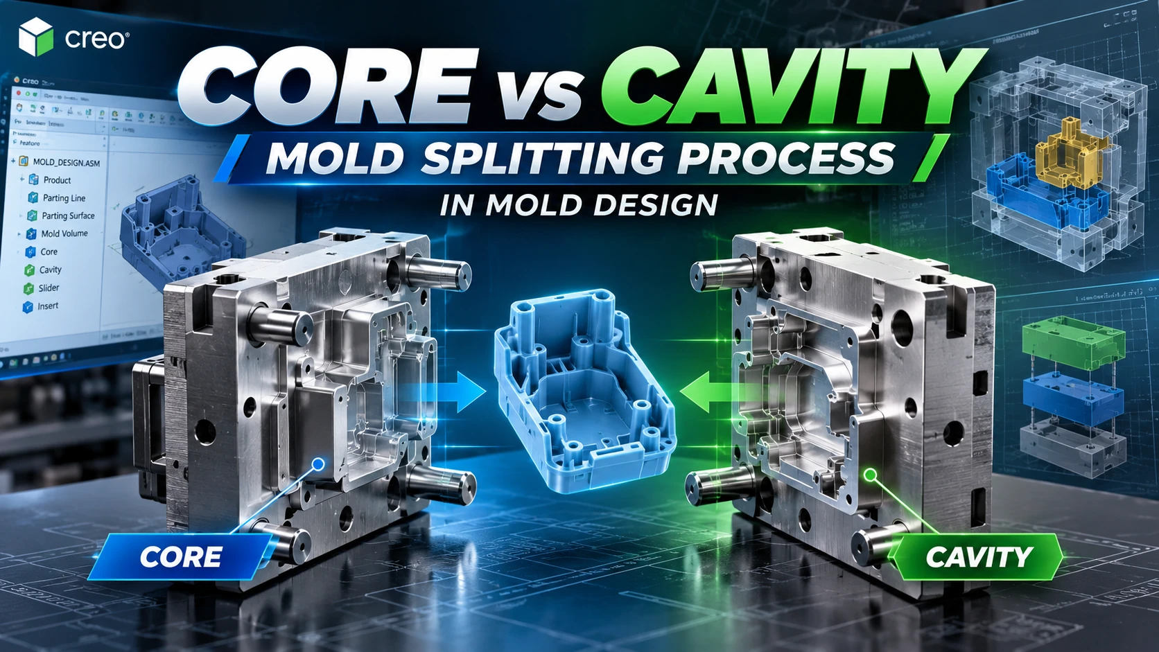
Consider a manufacturer developing a plastic injection mold. The design team creates core and cavity geometry, while the CAM team prepares roughing, semi-finishing and finishing operations based on the mold model.
During the design review, an engineer modifies a corner radius in the cavity. In an associative CAD/CAM workflow, the manufacturing programmer can update affected geometry references, regenerate relevant toolpaths and rerun machining verification rather than starting again from an unrelated imported model.
The CAM team must still verify cutting tools, stock allowances, cutting depths, stepovers, workholding and collision risks. Post-processed NC output must be validated against the actual CNC machine.
This example illustrates a common engineering workflow rather than a measured customer case study.
Common Mistakes When Implementing CAD/CAM Integration
- Assuming every toolpath remains automatically valid after a design change.
- Failing to manage model revisions and manufacturing approvals.
- Choosing software without verifying the required post processor.
- Overlooking machine kinematics, fixtures, holders and simulation requirements.
- Failing to standardize cutting-tool libraries and machining procedures.
- Purchasing multi-axis capabilities without first defining actual production needs.
Engineering Perspective from CADCAM SOFTWARE: A meaningful CAD/CAM evaluation should include a real component and a controlled design revision. Review how the platform handles geometry updates, affected machining operations, toolpath regeneration, simulation and NC output. This provides more useful evidence than a demonstration using an unchanged model.
When Should Manufacturers Choose Integrated CAD/CAM?
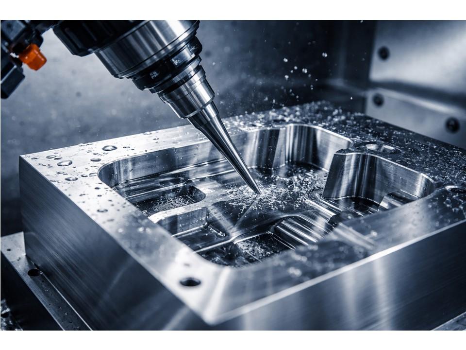 Integrated CAD/CAM is particularly valuable when products change frequently, engineering teams manage multiple revisions, mold and die geometries are complex, or design and CNC programming require close coordination.
For simple machining operations or established specialist workflows, manufacturers should compare the expected process benefits with software licensing, training, migration and implementation requirements.
5 Criteria for Choosing Integrated CAD/CAM Software
- CAD/CAM Associativity: Verify how machining references respond to design revisions.
- Machining Capabilities: Match available operations and machine-axis support to production requirements.
- Post Processing: Confirm compatibility with actual machine controllers and configurations.
- Simulation: Evaluate material-removal verification, interference checking and relevant safety requirements.
- Total Implementation Requirements: Review licensing, training, tool libraries, maintenance and technical support.
Organizations should also assess whether the platform fits their existing product data management and engineering change processes.
Frequently Asked Questions About Integrated CAD/CAM
What Is Integrated CAD/CAM?
Integrated CAD/CAM connects product design data with manufacturing programming in a shared or associative workflow, supporting more consistent use of engineering geometry.
How Is Integrated CAD/CAM Different from Separate Systems?
The main difference is the level of data connectivity, change propagation and manual file exchange required between design and manufacturing tools.
Can Integrated CAD/CAM Generate G-code?
CAM software can produce machine-specific NC programs through a suitable post processor, but machining operations and output still require engineering validation.
Do Toolpaths Update Automatically After CAD Changes?
Associated CAM features may respond to design changes, but affected toolpaths still need regeneration, simulation and approval where required.
Is Integrated CAD/CAM Suitable for Mold Manufacturing?
Yes. Associative workflows can help manage revisions between core and cavity design and the preparation of CNC machining operations.
Does PTC Creo Support Integrated CAD/CAM?
Yes. PTC Creo offers integrated manufacturing capabilities through suitable CAM packages and extensions.
Does Every Manufacturer Need All Creo CAM Extensions?
No. The appropriate configuration depends on machining methods, equipment, user requirements and the intended engineering workflow.
Does Integrated CAD/CAM Replace CNC Programmers?
No. Engineers remain responsible for machining strategies, tool selection, process validation and safe machine operation.
Explore Integrated CAD/CAM Solutions with CADCAM SOFTWARE
Selecting CAD/CAM software should begin with your manufacturing requirements, including product complexity, engineering revisions, CNC machines and programming methods.
CADCAM SOFTWARE helps manufacturers explore PTC Creo solutions, discuss demonstration requirements and request official licensing information based on their needs.
Hotline: +84 907 858 000 | Email: info@cadcamsoftware.vn
Explore Creo CAM software and the official PTC Creo extensions.