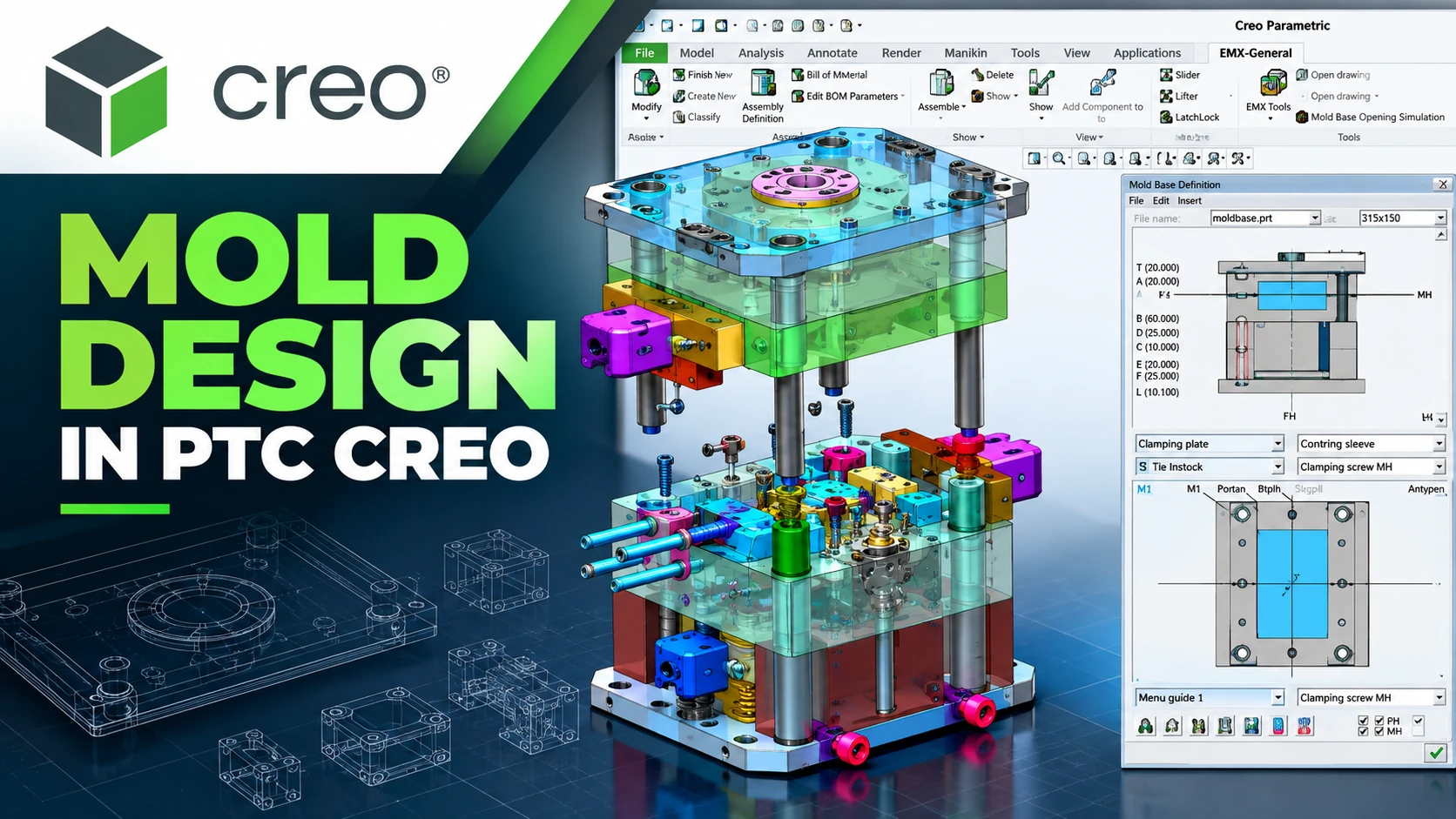
What Is Creo Mold Design? Mold Design Workflow in PTC Creo
Creo Mold Design is a mold design workflow within the PTC Creo ecosystem that enables engineers to develop tooling directly from 3D product models. Rather than treating product design and mold design as separate processes, Creo helps maintain the relationships between product geometry, core and cavity, moldbase, and manufacturing data.
For mold manufacturers, the value of a mold design system extends beyond 3D modeling. Engineers also need to address draft angles, pull direction, parting lines, parting surfaces, cores, cavities, inserts, sliders, moldbases, runners, gates, cooling, and design changes throughout product development.
PTC offers specialized tools such as Creo Tool Design Extension, Creo Expert Moldbase Extension, and Creo Mold Analysis Extension to support different stages of the mold development process.
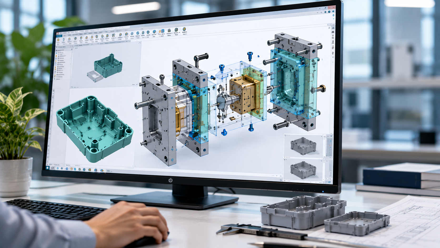
What Is Creo Mold Design?
Creo Mold Design refers to a set of workflows and tools within PTC Creo for developing molds from product models through to tooling. The process may include manufacturability checks, defining the pull direction, creating parting lines and surfaces, separating the core and cavity, building the moldbase, and preparing manufacturing data.
Companies looking to establish this workflow can explore the Creo Mold design solution implemented by CADCAM SOFTWARE.
The overall workflow can be summarized as follows:
Product Design → Draft & Pull Direction → Parting Line → Parting Surface → Core / Cavity → Moldbase → Mold Analysis → CAM / Manufacturing
Why Should Mold Design Stay Linked to the Product Model?
In a typical project, the product model may change several times before production begins. Changes to dimensions, ribs, bosses, holes, wall thickness, draft, or surfaces can directly affect the tooling.
If product design and mold design are managed using independent datasets, each engineering change may require manual tooling checks and modifications.
Creo Tool Design uses an associative workflow to maintain the relationship between product design and tooling. When the source geometry changes, engineers can manage its impact on the mold rather than relying entirely on rebuilding geometry.
Mold Design Workflow in PTC Creo
A typical mold design workflow in PTC Creo can be organized into the following steps.
Step 1: Prepare the 3D Product Model
The process begins with a 3D product model. Engineers can create the model directly in Creo or use CAD data supplied by the customer as the basis for tooling development.
Before splitting the mold, engineers should check:
- The overall product geometry.
- Wall thickness.
- Draft angles.
- Undercuts.
- Ribs, bosses, and other critical features.
- Complex surfaces.
- The direction in which the part will be released from the mold.
- Areas that may cause molding difficulties.
For companies handling both product design and tooling, keeping the data within the same Creo ecosystem helps create a more consistent workflow.
Step 2: Define the Pull Direction and Check Draft
The pull direction is the direction in which the part is released from the mold. Defining the mold opening direction directly affects the parting geometry, core and cavity, and mechanisms used to handle undercuts.
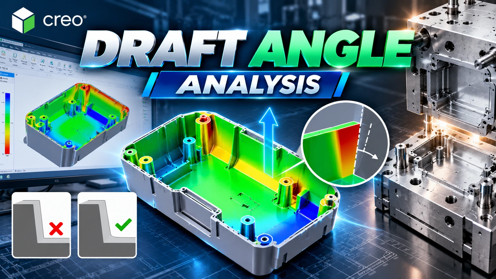
Draft angles should also be checked at this stage. Surfaces with insufficient or unsuitable draft should be identified before engineers invest significant time in tooling development.
Step 3: Define the Parting Line
The parting line defines the boundary between mold sections and provides the basis for creating the parting surface.
For products with complex surfaces, ribs, bosses, undercuts, or demanding cosmetic requirements, the parting line should be selected with both mold release and tooling manufacture in mind.
Step 4: Create the Parting Surface
Using the parting line, engineers develop a parting surface that establishes the geometric boundary for separating the core and cavity.
PTC Creo Tool Design provides tools for creating parting lines and parting surfaces within the tooling design workflow.
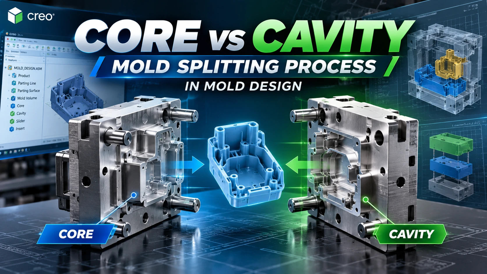
Step 5: Separate the Core and Cavity
Once the parting geometry is complete, the tooling geometry is divided into the core and cavity.
Depending on the product structure, the design may also require inserts, sliders, and additional components to handle undercuts or complex geometry.
A key advantage of Creo Tool Design is its ability to maintain associativity between the product design and tooling.
Step 6: Design Inserts, Sliders, and Other Tooling Components
Not every product can be molded using only a core and cavity. Undercuts, transverse holes, and special features may require sliders, inserts, or other tooling mechanisms.
Creo Tool Design supports the development of these components in the same environment as the core and cavity.
Step 7: Design the Moldbase
After completing the core and cavity, engineers continue developing the mold assembly. The moldbase may include mold plates, ejector pins, guides, screws, cooling components, and other standard parts.
Creo Expert Moldbase Extension (EMX) focuses on automating moldbase design tasks. It combines a 2D workflow with 3D model creation and component libraries to reduce repetitive design work.
Step 8: Design Runners, Gates, and Cooling
A complete injection mold also requires material delivery and cooling systems. Common mold components and systems include:
- Sprues.
- Runners.
- Gates.
- Cooling channels / waterlines.
- Ejection systems.
- Sliders and inserts.
Creo Tool Design supports workflows involving runners, gates, sprues, and waterlines, while Creo Expert Moldbase adds automation for many detailed moldbase components.
Step 9: Analyze Injection Molding Performance
Before manufacturing the tooling, companies can use Creo Mold Analysis Extension to evaluate injection molding directly on the engineering model.
Analysis results may be used to assess:
- Melt-front progression and filling behavior.
- Fill pressure.
- Short shots.
- Weld lines.
- Air traps.
- Sink marks.
- Temperature.
- Shrinkage.
- Fiber orientation, where applicable.
This analysis provides additional engineering data before the company invests in manufacturing the physical mold.
Step 10: Transfer the Design to CAM and CNC Machining
Once the design is complete, the core, cavity, inserts, and other tooling components move into manufacturing.
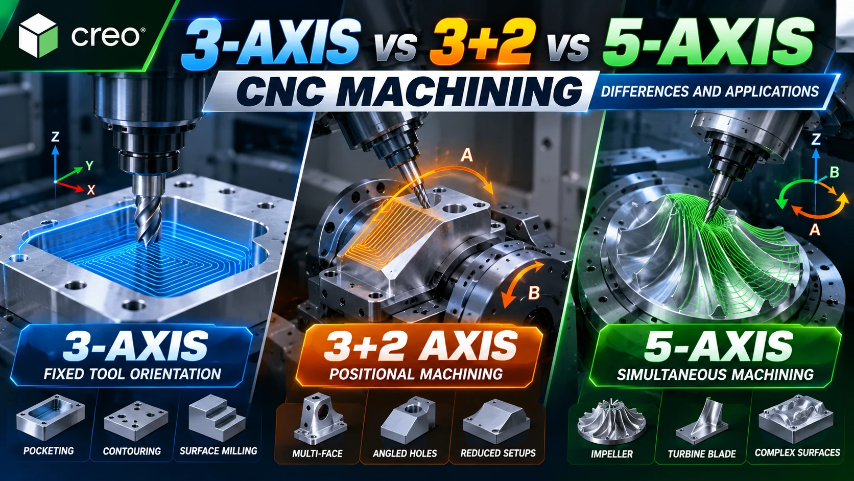
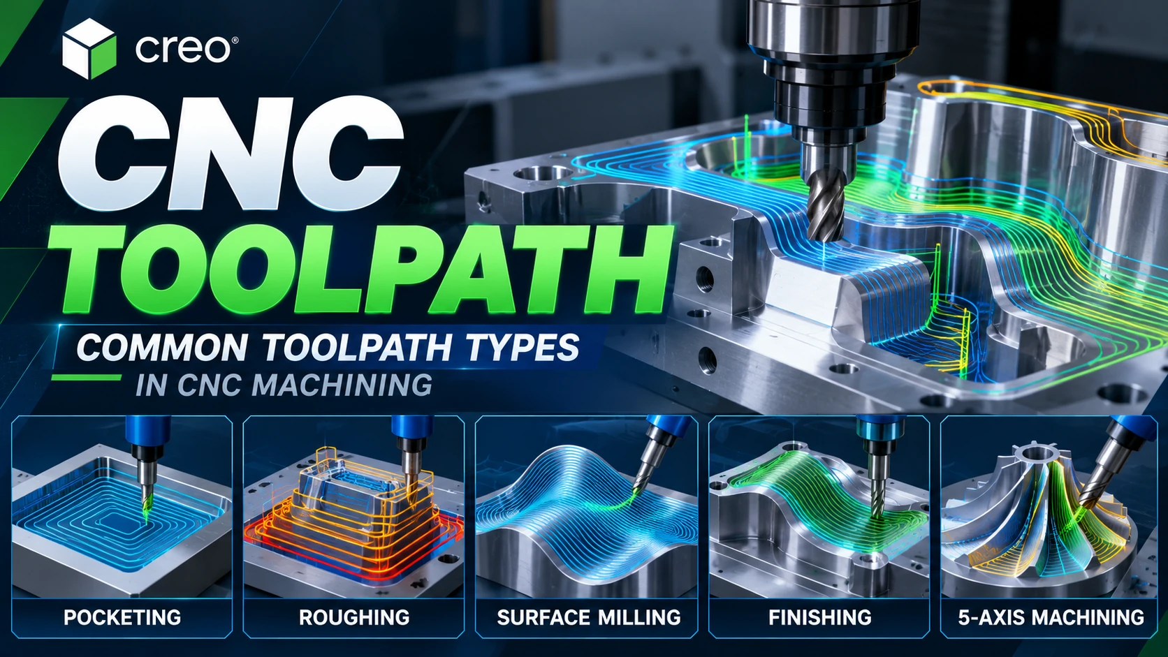
Within the PTC Creo ecosystem, Creo CAM software supports the development of CNC machining processes using CAD data.
The workflow can be extended as follows:
Creo CAD → Creo Mold Design → Creo CAM → CNC Manufacturing
What Does Creo Tool Design Extension Support?
Creo Tool Design Extension is a specialized tool for mold and casting tooling within the Creo environment.
- Creating parting lines.
- Creating parting surfaces.
- Separating cores and cavities.
- Developing sliders and inserts.
- Checking draft and thickness.
- Adding runners, gates, sprues, and waterlines.
- Maintaining associative updates between product design and tooling.
- Preparing drawings, bills of materials (BOMs), and related deliverables.
For further technical information, visit PTC’s official Creo Tool Design Extension page.
What Is Creo Expert Moldbase Extension Used For?
Creo Expert Moldbase Extension focuses on detailed moldbase design after the core and cavity have been defined.
It supports tasks such as:
- Creating 3D moldbases from a 2D workflow.
- Using component and supplier libraries.
- Positioning ejector pins.
- Designing waterlines.
- Placing screws, guides, plates, and other components.
- Generating BOMs and production drawings.
EMX is particularly relevant for companies that design multiple molds, use a large number of standard components, or want to standardize workflows across their mold design teams.
How Does Creo Mold Analysis Help Before Tooling Manufacture?
Creo Mold Analysis adds injection molding simulation capabilities directly within the Creo environment.
Rather than evaluating geometry only after the mold has been manufactured, engineers can investigate risks related to filling, short shots, air traps, weld lines, sink marks, shrinkage, and other parameters during design development.
The aim is not to replace a mold engineer’s experience, but to provide additional information that helps the engineering team evaluate design options before incurring tooling manufacturing costs.
How Does Creo Mold Design Differ from General 3D CAD?
| General 3D CAD | Creo Mold Design |
|---|---|
| Product Modeling | Product + Tooling |
| Surface Modeling | Parting Geometry |
| Solid Modeling | Core / Cavity |
| Assembly | Moldbase |
| Geometry Validation | Draft / Thickness / Moldability |
| Product Design | Injection Mold Workflow |
| 3D Model | Tooling Deliverables |
Creo Mold Design therefore goes beyond creating a 3D mold model. It also establishes a flow of data from product design through tooling and manufacturing.
Which Creo Mold Solution Should You Choose?
| Requirement | Solution |
|---|---|
| Parting Line / Parting Surface | Creo Tool Design Extension |
| Core / Cavity | Creo Tool Design Extension |
| Slider / Insert | Creo Tool Design Extension |
| Moldbase Design | Creo Expert Moldbase Extension |
| Standard Components | Creo Expert Moldbase Extension |
| Injection Molding Analysis | Creo Mold Analysis Extension |
| Core / Cavity Machining | Creo CAM |
Companies should choose a configuration based on their actual workflow rather than implementing every module by default:
Product Type → Mold Type → Geometry → Number of Projects → Level of Automation → Mold Analysis → CAM
Which Businesses Can Benefit from Creo Mold Design?
Plastic Mold Design and Manufacturing Companies
Companies developing injection molds, plastic housings, connectors, household products, and engineering plastic components can use Creo Mold workflows to connect product geometry with tooling.
Automotive and Motorcycle Component Suppliers
Automotive projects often require strict control over engineering changes and geometry. An associative workflow helps engineering teams manage the relationship between product design and tooling.
Electrical and Electronics Manufacturers
Plastic housings, connectors, enclosures, and precision molded components often require accurate control of draft, surfaces, parting geometry, and tooling.
Tooling and Mold Manufacturers
Specialist mold manufacturers can combine Creo Tool Design, Creo Expert Moldbase, and Creo CAM to develop a workflow covering core and cavity design, moldbase development, and CNC machining.
 Benefits of an Integrated Creo Mold Workflow
- Maintains the relationship between product geometry and tooling.
- Reduces reliance on intermediate file conversions.
- Makes engineering changes easier to manage.
- Standardizes parting and core/cavity workflows.
- Automates many moldbase design tasks.
- Evaluates moldability before tooling manufacture.
- Connects mold design with CNC machining data.
- Reduces the need to rebuild geometry when designs change.
Frequently Asked Questions About Creo Mold Design
What Is Creo Mold Design?
Creo Mold Design is a workflow and set of tools within PTC Creo for developing molds from 3D product models, including parting geometry, cores and cavities, moldbases, and related tooling tasks.
What Is Creo Tool Design Used For?
Creo Tool Design Extension supports mold and casting tooling design, including parting lines and surfaces, core and cavity separation, sliders, inserts, runners, gates, and waterlines.
How Does Creo Expert Moldbase Differ from Creo Tool Design?
Tool Design focuses on parting geometry and core/cavity development, while Expert Moldbase focuses on automating moldbase construction and the placement of related components.
What Problems Can Creo Mold Analysis Identify?
Creo Mold Analysis helps evaluate injection molding issues such as short shots, weld lines, air traps, sink marks, shrinkage, and parameters related to the filling process.
Can PTC Creo Be Used to Design Runners and Cooling Systems?
Yes. Creo tooling tools support workflows involving runners, gates, sprues, and cooling waterlines. Specific capabilities depend on the extensions and Creo configuration being used.
Can Creo Mold Designs Be Used for CNC Machining?
Yes. Creo CAM can be used in the subsequent workflow to develop CNC machining operations and toolpaths from Creo design data.
Creo Mold Solution Consulting for Your Business
CADCAM SOFTWARE helps companies evaluate PTC Creo solutions based on their actual mold design and manufacturing processes, from product design, parting geometry, core/cavity development, and moldbase design to injection molding analysis and CNC programming.
Before selecting a suitable Creo configuration, companies should identify their mold types, number of users, current workflows, and technical bottlenecks.
CADCAM SOFTWARE
Hanoi Office: No. 25, Alley 34, Giap Nhat Street, Thanh Xuan Ward, Hanoi, Vietnam
Ho Chi Minh City Office: Room 1508, Tower A, Masteri Centre Point, N2 Street, Long Binh Ward, Ho Chi Minh City, Vietnam
Tel: 024 6673 7986
Hotline: 0907 658 000
Email: info@cadcamsoftware.vn
Website: cadcamsoftware.vn