What Is Creo Mold Analysis? Injection Molding Simulation Bef
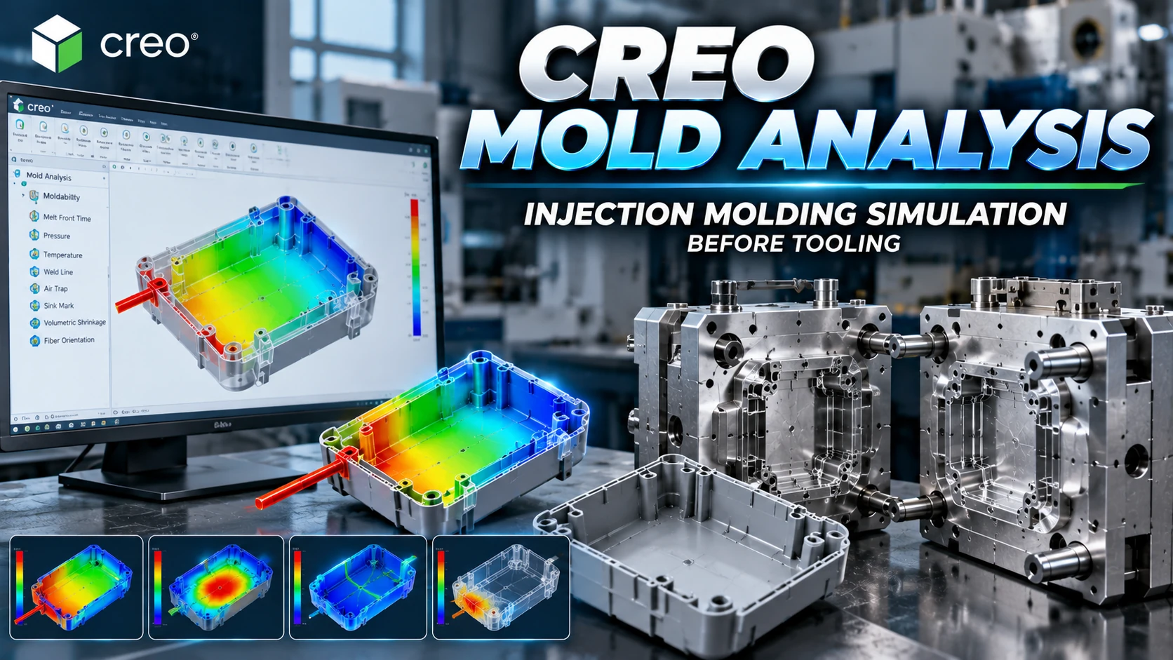
What Is Creo Mold Analysis? Creo Mold Analysis (CMA) is an injection molding simulation application integrated into PTC Creo. It enables engineers to evaluate plastic moldability, simulate melt flow and identify potential molding issues before manufacturing tooling. By analyzing melt-front progression, pressure, temperature and predicted defects, engineering teams can assess product and gating decisions earlier in development.
A plastic component may be geometrically correct in CAD yet remain difficult to manufacture by injection molding. Wall thickness, gate placement, polymer properties and processing conditions all influence filling behavior. Simulation provides a way to compare alternatives before committing to core, cavity and moldbase manufacturing.
With PTC Creo Parametric, designers can work with product geometry and moldability analysis in an integrated engineering environment.
What Is Creo Mold Analysis in PTC Creo?
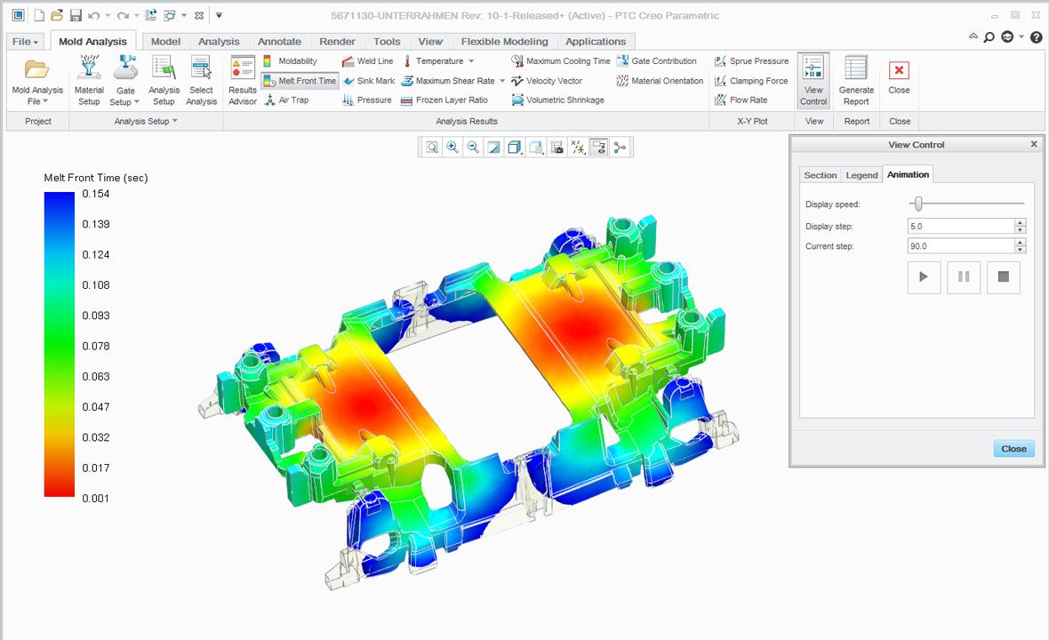 Creo Mold Analysis is designed to simulate the injection molding filling process and assess whether a plastic part can be filled under specified material and process conditions. Engineers define the product geometry, polymer material, injection gates and relevant processing parameters before running the analysis.
The results help explain how molten plastic advances through the part cavity, where filling resistance may be significant and where molding defects may develop. The simulation supports design decisions but does not replace physical mold trials or production validation.
Why Perform Injection Molding Simulation Before Tooling?
Identify Incomplete Filling Risks
Simulation helps reveal regions that may be difficult to fill, reducing the likelihood that short-shot risks remain undiscovered until mold trials.
Evaluate Gate Placement
Gate location influences flow length, filling balance, melt-front behavior and the position of potential weld lines. Comparing alternatives can help engineers select a more suitable gating strategy.
Predict Weld Lines and Air Traps
Predicted weld-line and air-trap locations provide useful information for assessing appearance, structural requirements and mold venting strategies.
Review Pressure and Temperature
Pressure and temperature results help engineers evaluate processing requirements and identify regions associated with unfavorable filling conditions.
Reduce Late Tooling Changes
Identifying moldability concerns before cutting steel provides more opportunities to revise product geometry, gate placement or process assumptions.
What Can Creo Mold Analysis Evaluate?
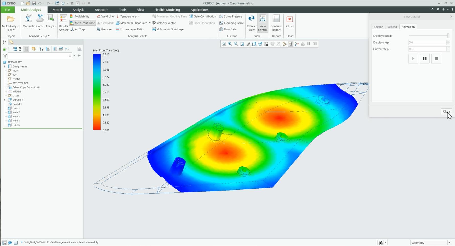
| Result | Engineering Purpose |
|---|---|
| Moldability | Assess regional filling feasibility |
| Melt Front Time | Visualize filling sequence |
| Pressure | Evaluate pressure distribution |
| Temperature | Review thermal conditions |
| Weld Line | Identify potential melt-front meeting locations |
| Air Trap | Identify potential trapped-air regions |
| Sink Mark | Assess surface-depression risk |
| Volumetric Shrinkage | Review predicted shrinkage distribution |
| Fiber Orientation | Evaluate orientation in reinforced polymers |
| Shear Rate / Stress | Assess polymer flow-related risks |
Available outputs depend on the software configuration, analysis settings and material data. Cooling-time estimates and shrinkage results should not automatically be interpreted as complete cooling-system or warpage validation.
How Does Mold Filling Analysis Work?
Mold Filling Analysis simulates the movement of molten polymer from the injection gate through the product cavity. The flow depends on cavity geometry, wall thickness, material viscosity, temperature and process conditions.
Thin sections and long flow paths can increase filling resistance, while differences in wall thickness can cause uneven melt-front progression. Engineers review simulation plots and contour maps to understand these effects and compare design alternatives.
7 Steps to Run Creo Mold Analysis
Step 1: Prepare the 3D CAD Model
Open the plastic part in Creo Parametric and verify the intended product revision, wall thickness, ribs, bosses and other relevant geometry.
Step 2: Open the Mold Analysis Application
Launch Mold Analysis from the Applications environment according to the installed Creo version and user interface.
Step 3: Select the Polymer Material
Choose a suitable material from the library, preferably matching the actual resin grade planned for production.
Step 4: Define Gate Locations
Specify one or more candidate injection gates. Different configurations can be evaluated to compare filling patterns and potential defects.
Step 5: Configure Process Conditions
Set filling time, melt temperature, mold temperature, maximum injection pressure and appropriate mesh resolution. Use process assumptions that reflect the intended manufacturing conditions.
Step 6: Run the Simulation
Execute the analysis and, where useful, create multiple runs with different gates or processing parameters.
Step 7: Interpret and Improve the Design
Review moldability, melt-front time, pressure, temperature, weld lines, air traps and other relevant results. Identify engineering concerns, adjust the design or process setup and rerun the simulation.
How to Evaluate Gate Location
Gate placement should be evaluated against filling balance, flow length, pressure requirements, weld-line locations, air-trap risk and appearance constraints. A convenient runner layout is not necessarily the best solution for product quality.
For a plastic electronics enclosure with ribs and bosses, two candidate gate locations may generate different filling patterns. The preferred option should be selected from the overall engineering results rather than the shortest filling time alone.
For multi-gate configurations, gate contribution and flow balance are additional considerations.
Common Injection Molding Defects Identified by Simulation
Short Shot
A short shot occurs when the cavity is not completely filled. Potential contributing factors include flow resistance, material properties, pressure, temperature and part geometry.
Weld Line
Weld lines form where separate melt fronts meet. Their impact depends on polymer behavior, local processing conditions and the structural requirements of the product.
Air Trap
Air traps are regions where air may become enclosed during filling. Their predicted locations can inform gating and venting decisions.
Sink Mark
Sink marks are surface depressions associated with shrinkage and local geometry, often requiring attention near thicker sections, ribs and bosses.
Shrinkage and Dimensional Risk
Volumetric shrinkage results can reveal nonuniform shrinkage trends. They should not be treated as a complete prediction of final part warpage.
Creo Mold Analysis vs Creo Mold Design
| Factor | Creo Mold Analysis | Creo Mold Design |
|---|---|---|
| Purpose | Evaluate injection molding behavior | Develop tooling geometry |
| Inputs | Part, polymer, gates and process conditions | Part geometry, parting surfaces and workpiece |
| Outputs | Simulation maps and engineering indicators | Core, cavity, inserts and tooling components |
| Primary Value | Early moldability validation | Tooling design and manufacturing preparation |
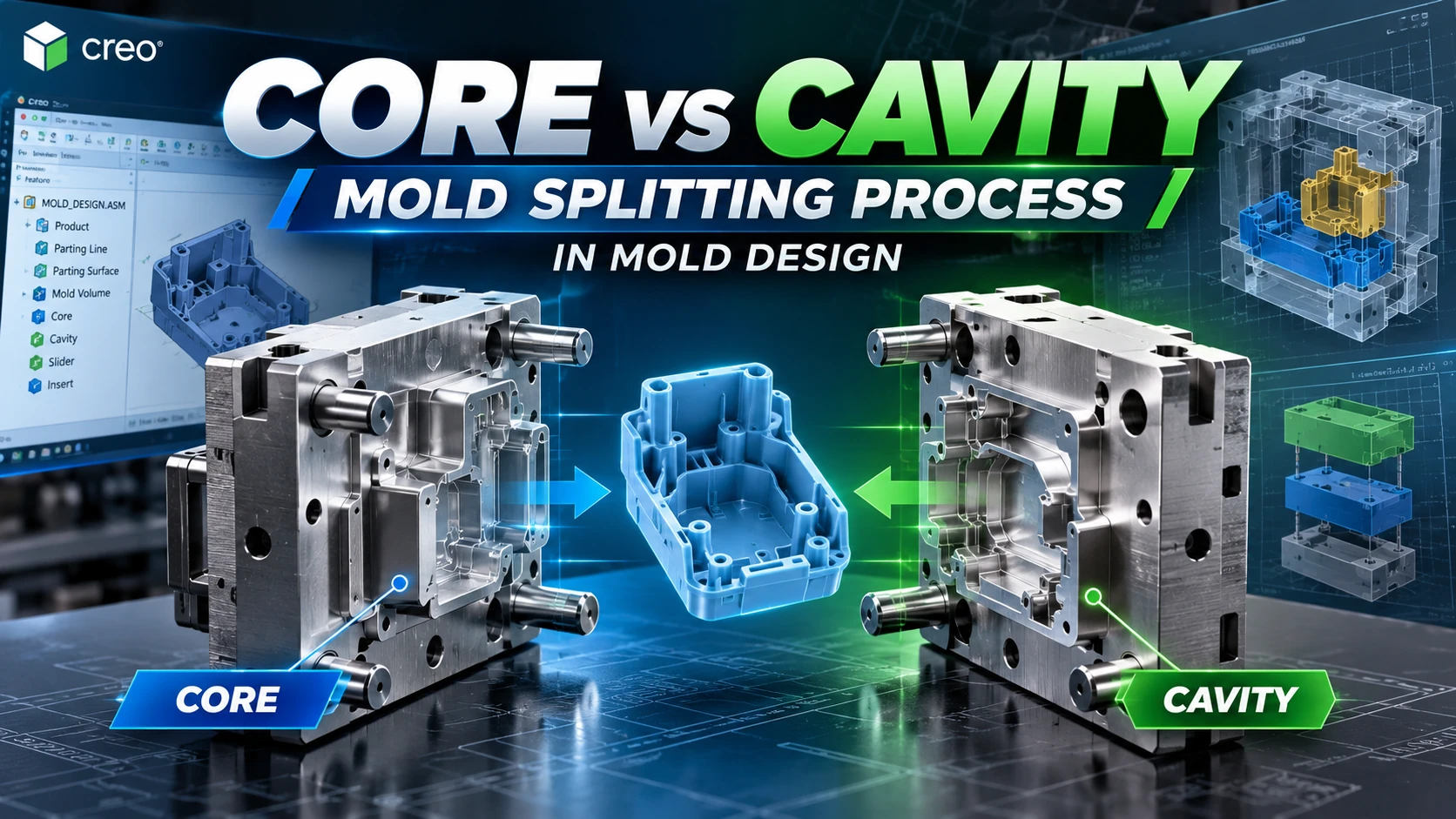
These applications serve complementary roles. Mold Analysis evaluates the molding process, while mold-design tools develop the physical tooling geometry required for manufacturing.
From Injection Molding Simulation to CNC Manufacturing
A practical engineering workflow can follow Product CAD → Moldability Review → Mold Analysis → Design Revision → Parting Surface → Core/Cavity → Moldbase → CAM → CNC Manufacturing → Mold Trial.
Simulation findings may influence product geometry and gating decisions before core and cavity development. Once tooling geometry is finalized, manufacturers can use Creo CAM for CNC machining preparation.
Physical mold trials remain necessary because actual processing conditions and material behavior may differ from the simulation assumptions.
Engineering Example: Plastic Electronics Housing
Consider a plastic electronics housing with thin walls, internal ribs, screw bosses and connector openings. The engineering team needs to assess whether the cavity can be filled, where weld lines may occur and whether the expected pressure is compatible with the intended process.
The team compares gate alternatives using the same relevant material assumptions and reviews melt-front time, pressure, weld-line and air-trap results. If a candidate creates unfavorable filling conditions, the engineers can evaluate another gate location, modify part geometry or adjust the process setup.
This is an illustrative engineering scenario, not a verified CADCAM SOFTWARE customer case study.
When Should Manufacturers Use Creo Mold Analysis?
- During early development of new injection-molded plastic products.
- For thin-wall components, long flow paths and complex internal features.
- When comparing alternative gate positions or filling conditions.
- For parts with critical appearance or structural requirements.
- When product-design and mold-engineering teams need simulation-based design reviews.
Engineering Perspective from CADCAM SOFTWARE: Reliable simulation begins with suitable input data. Resin grade, wall thickness, gate assumptions and processing conditions should reflect the intended manufacturing scenario. A visually convincing contour plot is not sufficient evidence of moldability when the inputs are incorrect.
Limitations of Injection Molding Simulation
Simulation accuracy depends on geometry quality, polymer data, process assumptions, meshing and interpretation. It supports engineering decisions but does not guarantee defect-free production.
Detailed cooling-system optimization, full warpage assessment and production-cycle validation should be evaluated against the capabilities of the specific software version and license configuration. Do not assume that every advanced injection molding simulation capability is included in a basic Creo license.
Frequently Asked Questions
 What Is Creo Mold Analysis?
Creo Mold Analysis is an injection molding simulation application in PTC Creo used to evaluate mold filling and predict selected molding defects before tooling development.
Can Creo Mold Analysis predict short shots?
Yes. Moldability and filling analysis can identify regions that may not fill completely under the simulated conditions.
Can it predict weld lines and air traps?
Yes. The application provides results indicating potential weld-line and trapped-air locations.
Can engineers compare different gate locations?
Yes. Multiple gate configurations and processing conditions can be analyzed to compare filling behavior and related results.
Does Creo Mold Analysis replace mold trials?
No. Physical mold trials and manufacturing validation remain necessary.
Is Creo Mold Analysis the same as Creo Mold Design?
No. Mold Analysis focuses on molding simulation, while mold-design tools develop physical tooling geometry.
Does Creo Mold Analysis require additional licensing?
Access depends on the PTC product package and licensing configuration. The appropriate extension or suite should be confirmed before purchase.
Who benefits from Creo Mold Analysis?
Plastic product designers, R&D engineers, mold designers and injection molding manufacturers can use it to evaluate moldability earlier in development.
Explore Creo Mold Analysis Solutions with CADCAM SOFTWARE
CADCAM SOFTWARE helps engineering teams evaluate PTC Creo solutions for plastic part design, injection molding analysis, mold tooling and CNC manufacturing.
Contact us to discuss demonstrations, technical requirements and official software licensing options. The appropriate configuration depends on the required capabilities, user count and engineering workflow.
Hotline: +84 907 858 000 | Email: info@cadcamsoftware.vn
Learn more from the official Creo Mold Analysis Extension page and PTC Creo Mold Analysis documentation.