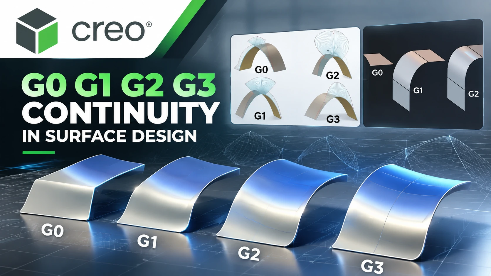
What Are G0, G1, G2 and G3 Continuity in Surface Design?
G0 G1 G2 G3 Continuity describes different levels of
geometric continuity between curves or surfaces. In surface design,
having two surfaces meet at the same boundary is often only the beginning.
Engineers may also need to control tangent direction, curvature and the
rate at which curvature changes across the connection.
In PTC Creo Style, the primary continuity levels are
G0 – Position, G1 – Tangent,
G2 – Curvature and G3 – Acceleration.
Each level introduces additional geometric requirements at the connection
between surfaces.
Understanding these continuity levels helps engineers select the appropriate
condition for each surface region instead of automatically applying G2 or G3
everywhere. The correct choice depends on design intent, product geometry
and surface quality requirements.
What Is Surface Continuity?
Surface Continuity describes the geometric relationship
between two surfaces along a shared boundary. Depending on the design
requirement, the surfaces may only need to meet at the same position or may
also need to maintain tangent direction, curvature and the rate of curvature
change.
The four primary levels can be summarized as:
G0 Position → G1 Tangent → G2 Curvature → G3 Acceleration
A higher continuity level introduces additional geometric conditions.
However, this does not mean that G3 should always be used. The appropriate
level depends on product function, geometry, design intent and the required
surface quality.
 What Is G0 Continuity – Position Continuity?
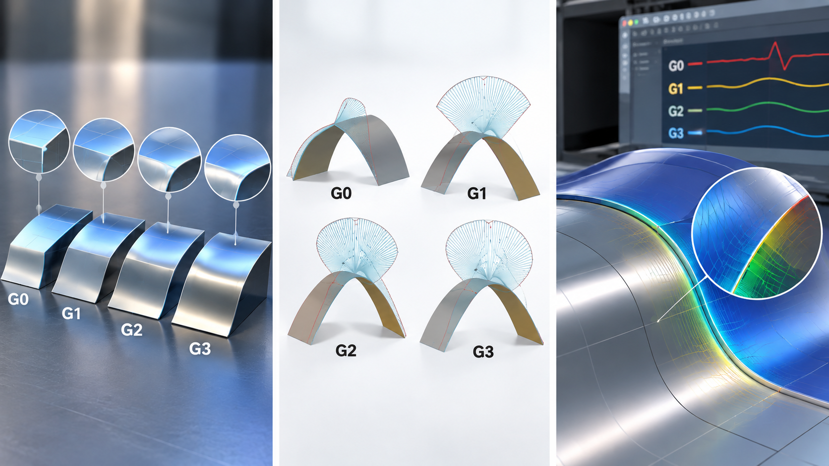
G0 Continuity, or Position Continuity, is the basic
continuity level. Two surfaces share a common boundary, but their tangent
directions and curvature do not have to match across that boundary.
In simple terms:
G0 = shared position at the boundary.
Characteristics of G0 Continuity
- The surfaces share a common boundary.
- Matching tangent direction is not required.
- Matching curvature is not required.
- A visible change in direction can occur at the connection.
G0 can be appropriate when the design intentionally requires a distinct
edge or a geometric transition that does not need tangent continuity.
What Is G1 Continuity – Tangent Continuity?
G1 Continuity is Tangent Continuity. In addition to
meeting along the same boundary, the two surfaces are tangent to each other
along their common boundary.
A simplified relationship is:
G1 = G0 + Tangent Continuity.
G1 creates a more controlled transition than G0 because the direction of
the surfaces is continuous across the connection. However, G1 does not
require the curvature on both sides of the boundary to match.
When Is G1 Continuity Used?
Tangent continuity can be suitable for transition surfaces, fillets and
other areas where the primary requirement is to avoid an abrupt directional
change at the connection.
For products with demanding visual appearance or surface reflection
requirements, however, G1 alone may not provide the required level of
surface control.
What Is G2 Continuity – Curvature Continuity?
G2 Continuity is Curvature Continuity. Two surfaces
satisfy G2 when they are tangent-continuous across their common boundary
and also share curvature along that boundary.
A simplified relationship is:
G2 = G1 + Curvature Continuity.
This is the key difference between G1 and G2. With G1, tangent direction
is maintained, but curvature can still change across the connection.
With G2, curvature at the boundary is also controlled.
Why Is G2 Important in Surface Design?
Curvature continuity is useful when engineers need a smoother transition
between surfaces, particularly in areas where product shape, visual
appearance and surface quality are important.
Typical applications may include:
- Complex product housings.
- Enclosures.
- Exterior product surfaces.
- Consumer products.
- Important transition surfaces.
- Industrial design applications.
What Is G3 Continuity – Acceleration Continuity?
G3 Continuity is referred to as Acceleration Continuity
in PTC Creo. At this level, the surfaces maintain tangent continuity,
share curvature at the boundary and also maintain the same rate of
curvature change.
A simplified relationship is:
G3 = G2 + Continuity of the Rate of Curvature Change.
G3 introduces a higher level of control than G2 and can be useful when a
very carefully controlled curvature transition is required.
In Creo Style, G3 Surface Acceleration connections are available when the
required geometric conditions are satisfied. Therefore, not every surface
connection can or needs to be defined as G3.
G0 vs G1 vs G2 vs G3 Continuity
| Level | Name | Main Condition | Connection Characteristic |
|---|---|---|---|
| G0 | Position | Shared boundary | Position continuous |
| G1 | Tangent | G0 + Tangent | Tangent continuous |
| G2 | Curvature | G1 + Curvature | Curvature continuous |
| G3 | Acceleration | G2 + Rate of curvature change | Higher-order curvature transition |
What Is the Difference Between G1 and G2 Continuity?
G1 and G2 are two continuity levels that are commonly confused when
engineers begin working with surface modeling.
With G1, the two surfaces maintain the same tangent
direction along their common boundary. This provides tangent continuity,
but the curvature on either side of the boundary can still be different.
With G2, tangent continuity is maintained and curvature
is also continuous at the boundary.
G1 controls tangency – G2 additionally controls curvature.
When evaluating surfaces that require a high level of smoothness,
engineers should not rely only on the shaded appearance of the model.
Geometric surface analysis tools can provide additional information about
the quality of the transition.
What Is the Difference Between G2 and G3 Continuity?
G2 requires curvature continuity at the boundary, while G3 introduces an
additional condition related to the rate at which curvature changes.
This means that a connection can satisfy G2 without necessarily satisfying
G3.
G3 can be useful in areas where the curvature transition must be controlled
more carefully. However, a higher continuity level also introduces
additional geometric constraints.
For this reason, the objective should not be:
“Every surface must be G3.”
Instead, engineers should select the appropriate continuity level according
to the design intent and requirements of each surface region.
Is Higher Surface Continuity Always Better?
Not necessarily.
G0, G1, G2 and G3 should not simply be treated as a quality scale where
G3 is automatically better than every lower level. Each level describes
a different geometric condition at the connection.
For example, if the product requires a deliberate edge, G0 may be the
correct condition. If the design requires a tangent transition, G1 may be
sufficient. When curvature quality is important, G2 or G3 may be considered.
Applying unnecessarily high continuity can also introduce additional
constraints and make the desired surface shape more difficult to control.
How to Check Surface Continuity in PTC Creo
When working with surface modeling, viewing a shaded model is only one
part of the evaluation process. Engineers can also use geometric analysis
tools to understand the quality of transitions between curves and surfaces.
1. Check the Connection Type
In Creo Style, surface connections can be defined as G0 Position,
G1 Tangent, G2 Curvature or G3 Acceleration depending on the geometry
and the available connection conditions.
2. Use Curvature Plots
A Curvature Plot provides a graphical representation of curvature at
locations along a curve and can help engineers evaluate the smoothness
of curves used to construct surfaces.
Unexpected changes in curvature can indicate that the curve should be
refined before it is used to develop the final surface.
3. Analyze Surface Connections
Surface connection analysis can help engineers evaluate the geometric
relationship between connected surfaces and determine whether the
connection meets the required continuity condition.
This is particularly useful when a model appears visually smooth but the
underlying geometry does not satisfy the intended continuity requirement.
G0 G1 G2 G3 Continuity in Product Design
The required continuity level depends on the purpose of each surface.
| Design Requirement | Continuity to Consider |
|---|---|
| Intentional geometric edge | G0 |
| Tangent transition | G1 |
| Smooth curvature transition | G2 |
| More controlled rate of curvature change | G3 |
The table above provides conceptual guidance rather than fixed engineering
rules. The appropriate continuity level depends on product function,
design intent, manufacturing requirements and desired surface quality.
Why Does Surface Continuity Matter in Mold Design?
The quality of product surfaces can directly influence downstream tooling
development, particularly for products with complex geometry or demanding
appearance requirements.
For mold and die manufacturers, validating product surfaces before
developing parting geometry, core and cavity data can provide a better
starting point for the tooling workflow.
Surface continuity can therefore be relevant not only during product
styling but also when product geometry is transferred into mold design
and manufacturing processes.
Surface Modeling in PTC Creo
PTC Creo provides surface modeling capabilities alongside solid and
parametric modeling for products that require complex geometry or
controlled surface development.
In Creo Style, engineers can work with curves, surfaces and connection
constraints to create and refine product geometry.
Technical information about surface connection terminology is available
from
PTC Creo Help – Style
.
FAQ About G0 G1 G2 G3 Continuity
What is G0 Continuity?
G0, or Position Continuity, means that two surfaces share a common
boundary without requiring matching tangent direction or curvature.
What is G1 Continuity?
G1, or Tangent Continuity, means that two surfaces are tangent to each
other along their common boundary.
What is G2 Continuity?
G2, or Curvature Continuity, means that the surfaces maintain tangent
continuity and share curvature along their common boundary.
What is G3 Continuity?
G3 is called Acceleration Continuity in PTC Creo. In addition to tangent
and curvature continuity, it maintains the rate of curvature change across
the connection.
What is the difference between G1 and G2?
G1 controls tangent direction at the connection. G2 additionally requires
curvature continuity at the common boundary.
What is the difference between G2 and G3?
G2 maintains curvature continuity at the boundary, while G3 adds a
condition related to the rate of curvature change.
Should every surface use G3 Continuity?
No. The appropriate continuity level depends on the design intent and
requirements of each surface region. G0, G1 or G2 may be more appropriate
for many applications.
Does PTC Creo support G0, G1, G2 and G3?
Yes. Creo Style supports G0 Position, G1 Tangent, G2 Curvature and
G3 Acceleration connection types when the corresponding geometric
conditions are available.
Discuss PTC Creo Surface Design with CADCAM SOFTWARE
CADCAM SOFTWARE supports businesses evaluating PTC Creo for product design,
parametric modeling, surface modeling, mold design and related engineering
workflows.
For businesses working with complex product geometry, understanding surface
requirements, continuity conditions and engineering workflows can help
determine the appropriate Creo configuration for their actual design needs.
CADCAM SOFTWARE COMPANY LIMITED
Hanoi Office:
No. 25, Alley 34, Giap Nhat Street, Thanh Xuan Ward, Hanoi, Vietnam
Ho Chi Minh City Office:
R.1508, Tower A, Masteri Centre Point, N2 Street, Long Binh Ward,
Ho Chi Minh City, Vietnam
Tel: 024 6673 7986
Hotline: 0907 658 000
Email:
info@cadcamsoftware.vn