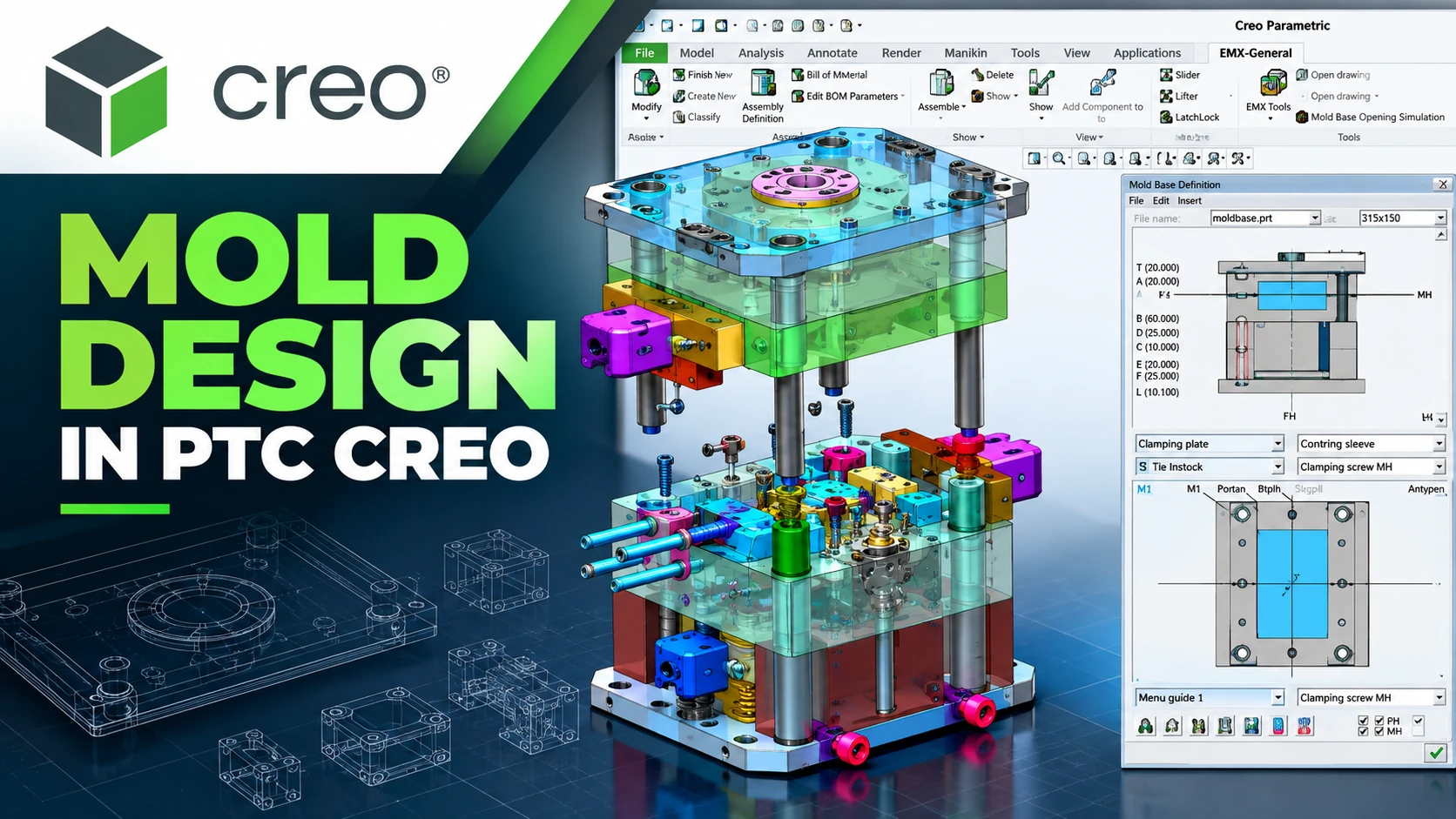
What Is Creo Mold Design? Mold Design Workflow in PTC Creo
PTC Creo Mold Design provides an integrated mold and tooling
design workflow within the Creo environment. It enables engineers to develop
tooling directly from 3D product geometry while maintaining relationships
between the product model, core and cavity geometry, moldbase components and
downstream manufacturing data.
For mold and die manufacturers, mold design involves much more than creating
3D solids. Engineers must consider pull direction, draft, parting lines,
parting surfaces, core and cavity geometry, sliders, inserts, moldbase
components, runners, gates, cooling systems and engineering changes.
PTC provides dedicated solutions including Creo Tool Design Extension,
Creo Expert Moldbase Extension and
Creo Mold Analysis Extension to support different stages
of this workflow.
What Is Creo Mold Design?
Creo Mold Design refers to the workflows and specialized tools used to
develop molds and manufacturing tooling within PTC Creo.
A typical workflow begins with the 3D product model and progresses through
geometry validation, pull-direction definition, parting geometry,
core/cavity splitting, moldbase development, mold analysis and manufacturing.
Product Design → Draft & Pull Direction → Parting Line →
Parting Surface → Core / Cavity → Moldbase → Mold Analysis →
CAM / Manufacturing
Why Is Associativity Important in Mold Design?
Product geometry often changes during development. Dimensions, ribs,
bosses, holes, wall thicknesses, draft angles and surfaces may be modified
before the product reaches production.
When product design and tooling are maintained as disconnected datasets,
each engineering change may require additional manual checking and rework.
Creo Tool Design provides associative workflows that help maintain the
relationship between product geometry and tooling data, allowing mold
designers to manage design changes more efficiently.
PTC Creo Mold Design Workflow
A typical Creo Mold Design workflow can be organized
into the following steps.
Step 1: Prepare the 3D Product Model
The process starts with the 3D product model. The model may be created
directly in Creo or received as CAD data from a customer for tooling
development.
Before developing the mold, engineers should review:
- Overall product geometry.
- Wall thickness.
- Draft angles.
- Undercuts.
- Ribs, bosses and critical features.
- Complex surfaces.
- The intended mold opening direction.
- Areas that may create molding or tooling challenges.
Step 2: Define Pull Direction and Check Draft
Pull direction determines how the molded component will
be removed from the tooling. It directly influences parting geometry,
core and cavity design and the need for sliders or other mechanisms.
Draft analysis should also be performed early to identify surfaces that
may create release or tooling challenges before significant engineering
time is invested in the mold design.
Step 3: Create the Parting Line
The parting line defines the boundary used to separate
the mold geometry and provides the basis for developing the parting surface.
For products with complex surfaces, ribs, bosses, undercuts or demanding
appearance requirements, the location of the parting line should be
evaluated together with mold release and tooling manufacturability.
Step 4: Build the Parting Surface
The parting surface is developed from the parting
geometry and provides the geometric boundary required to split the tooling
into the corresponding mold regions.
Creo Tool Design provides dedicated capabilities for creating parting
lines and parting surfaces as part of the mold design workflow.
Step 5: Split Core and Cavity
Once the parting geometry has been completed, the tooling can be divided
into core and cavity components.
Depending on the product geometry, additional inserts, sliders or other
tooling components may be required to handle undercuts and complex features.
An important aspect of Creo Tool Design is the ability to maintain
associativity between product design data and tooling geometry.
Step 6: Develop Inserts, Sliders and Tooling Components
Not every molded component can be produced using only two basic core and
cavity halves. Side holes, undercuts and other complex features may require
sliders, inserts or additional tooling mechanisms.
Creo Tool Design supports the development of these components within the
same engineering environment as the core and cavity geometry.
Step 7: Build the Moldbase
After core and cavity development, the tooling is integrated into the
moldbase. A moldbase may contain mold plates, ejector pins, guides, screws,
cooling components and many standardized parts.
Creo Expert Moldbase Extension (EMX) focuses on
automating moldbase development. It combines a process-driven workflow
with automatic 3D generation and component libraries to reduce repetitive
engineering tasks.
Step 8: Develop Runners, Gates and Cooling Systems
A complete injection mold also requires systems for material delivery,
cooling and part ejection.
Typical elements include:
- Sprues.
- Runners.
- Gates.
- Cooling channels and waterlines.
- Ejector systems.
- Sliders and inserts.
Creo tooling solutions support workflows related to runners, gates,
sprues and waterlines, while Creo Expert Moldbase can automate many
detailed moldbase components.
Step 9: Analyze Injection Molding
Before committing to physical tooling, engineers can use
Creo Mold Analysis Extension to evaluate the injection
molding process directly within the engineering workflow.
Analysis can help investigate:
- Melt-front and fill behavior.
- Fill pressure.
- Short shots.
- Weld lines.
- Air traps.
- Sink marks.
- Temperature.
- Shrinkage.
- Fiber orientation where applicable.
The objective is to provide additional engineering information before
the business commits resources to manufacturing the physical tooling.
Step 10: Move from Mold Design to CNC Manufacturing
Once the mold design has been completed, the core, cavity, inserts and
other tooling components need to move into manufacturing.
Within the PTC Creo ecosystem, Creo CAM can extend the workflow into CNC
programming and machining using the CAD geometry.
Creo CAD → Creo Mold Design → Creo CAM → CNC Manufacturing
What Does Creo Tool Design Extension Do?
Creo Tool Design Extension is a specialized solution for developing mold
and casting tooling within the Creo environment.
- Create parting lines.
- Create parting surfaces.
- Split core and cavity geometry.
- Develop sliders and inserts.
- Check draft and thickness.
- Develop runners, gates, sprues and waterlines.
- Maintain associative updates between design and tooling.
- Prepare drawings, BOMs and related tooling deliverables.
For additional technical information, visit
PTC Creo Tool Design Extension
.
What Is Creo Expert Moldbase Extension?
Creo Expert Moldbase Extension focuses on detailed
moldbase development after the core and cavity geometry has been defined.
It can support engineering tasks involving:
- 3D moldbase generation.
- Component and supplier libraries.
- Ejector pin placement.
- Waterline development.
- Screws, guides, plates and related components.
- BOM generation.
- Production drawings.
EMX can be particularly relevant to mold manufacturers that develop
multiple molds, use standardized components extensively or want to
standardize moldbase workflows across engineering teams.
What Does Creo Mold Analysis Provide?
Creo Mold Analysis adds injection molding simulation
capabilities to the Creo environment.
Instead of evaluating geometry only after physical tooling has been
manufactured, engineers can investigate potential fill problems, short
shots, air traps, weld lines, sink marks, shrinkage and other molding
conditions during product and tooling development.
The purpose is not to replace the experience of mold engineers. Analysis
provides additional engineering information that can support design
decisions before costly tooling changes are required.
Creo Mold Design vs. General-Purpose 3D CAD
| General 3D CAD | Creo Mold Design |
|---|---|
| Product Modeling | Product + Tooling |
| Surface Modeling | Parting Geometry |
| Solid Modeling | Core / Cavity |
| Assembly | Moldbase |
| Geometry Validation | Draft / Thickness / Moldability |
| Product Design | Injection Mold Workflow |
| 3D Model | Tooling Deliverables |
The objective of Creo Mold Design therefore goes beyond
creating a 3D mold model. It helps establish a workflow connecting product
design, tooling development and manufacturing.
Which Creo Mold Solution Does Your Business Need?
| Requirement | Creo Solution |
|---|---|
| Parting Line / Parting Surface | Creo Tool Design Extension |
| Core / Cavity | Creo Tool Design Extension |
| Slider / Insert | Creo Tool Design Extension |
| Moldbase Design | Creo Expert Moldbase Extension |
| Standard Components | Creo Expert Moldbase Extension |
| Injection Molding Analysis | Creo Mold Analysis Extension |
| Core / Cavity CNC Machining | Creo CAM |
Businesses should select the appropriate configuration according to
their actual engineering workflow rather than automatically deploying
every available module.
Product Type → Mold Type → Geometry → Project Volume →
Automation Requirements → Mold Analysis → CAM
Who Can Benefit from Creo Mold Design?
Injection Mold Design and Manufacturing Companies
Companies developing injection molds, plastic housings, connectors,
consumer products and engineering plastic components can use Creo Mold
workflows to connect product geometry with tooling development.
Automotive and Motorcycle Component Suppliers
Automotive projects often require strict control over geometry and
engineering changes. Associative workflows can help engineering teams
manage the relationship between product design and tooling.
Electronics and Electrical Manufacturers
Plastic housings, connectors, enclosures and precision molded components
often require careful control of draft, surfaces, parting geometry and
tooling accuracy.
Tooling and Mold Manufacturers
Mold and die manufacturers can combine Creo Tool Design, Creo Expert
Moldbase and Creo CAM to establish a workflow from core and cavity
development through moldbase design and CNC manufacturing.
 Benefits of an Integrated Creo Mold Workflow
- Maintain relationships between product and tooling geometry.
- Reduce dependence on intermediate CAD translation.
- Manage engineering changes more efficiently.
- Standardize parting and core/cavity workflows.
- Automate repetitive moldbase engineering tasks.
- Evaluate moldability before physical tooling is produced.
- Connect mold design with downstream CNC manufacturing.
- Reduce unnecessary geometry reconstruction when product designs change.
FAQ About Creo Mold Design
What is Creo Mold Design?
Creo Mold Design refers to PTC Creo workflows and specialized tools for
developing molds from 3D product geometry, including parting geometry,
core/cavity development, moldbase design and related tooling activities.
What is Creo Tool Design Extension used for?
Creo Tool Design Extension supports mold and casting tooling development,
including parting line and surface creation, core/cavity splitting,
sliders, inserts, runners, gates and waterlines.
What is the difference between Creo Tool Design and Creo Expert Moldbase?
Creo Tool Design primarily supports parting geometry, core/cavity and
other tooling development tasks, while Creo Expert Moldbase focuses on
detailed moldbase automation and standard component placement.
What can Creo Mold Analysis detect?
Creo Mold Analysis can help engineers evaluate injection molding
conditions and identify potential issues such as short shots, weld lines,
air traps, sink marks and other molding-related conditions.
Can PTC Creo be used to design runners and cooling systems?
Yes. Creo tooling solutions support workflows involving runners, gates,
sprues and cooling waterlines. The exact capabilities available depend
on the Creo extensions and configuration deployed.
Can Creo Mold Design connect to CNC machining?
Yes. Tooling geometry developed in Creo can continue into Creo CAM
workflows for CNC programming and manufacturing.
Discuss Your Creo Mold Requirements with CADCAM SOFTWARE
CADCAM SOFTWARE supports businesses in evaluating PTC Creo solutions
according to their actual mold design and manufacturing workflows,
from product design, parting geometry and core/cavity development to
moldbase design, mold analysis and CNC programming.
Before selecting a Creo configuration, businesses should identify their
mold types, number of users, current engineering workflow and major
technical bottlenecks.
CADCAM SOFTWARE COMPANY LIMITED
Hanoi Office: No. 25, Alley 34, Giap Nhat Street, Thanh Xuan Ward,
Hanoi, Vietnam
Ho Chi Minh City Office: R.1508, Tower A, Masteri Centre Point,
N2 Street, Long Binh Ward, Ho Chi Minh City, Vietnam
Tel: 024 6673 7986
Hotline: 0907 658 000
Email: info@cadcamsoftware.vn