PTC Creo CAE Licensed Software | Advanced Engineering Simulation Solutions

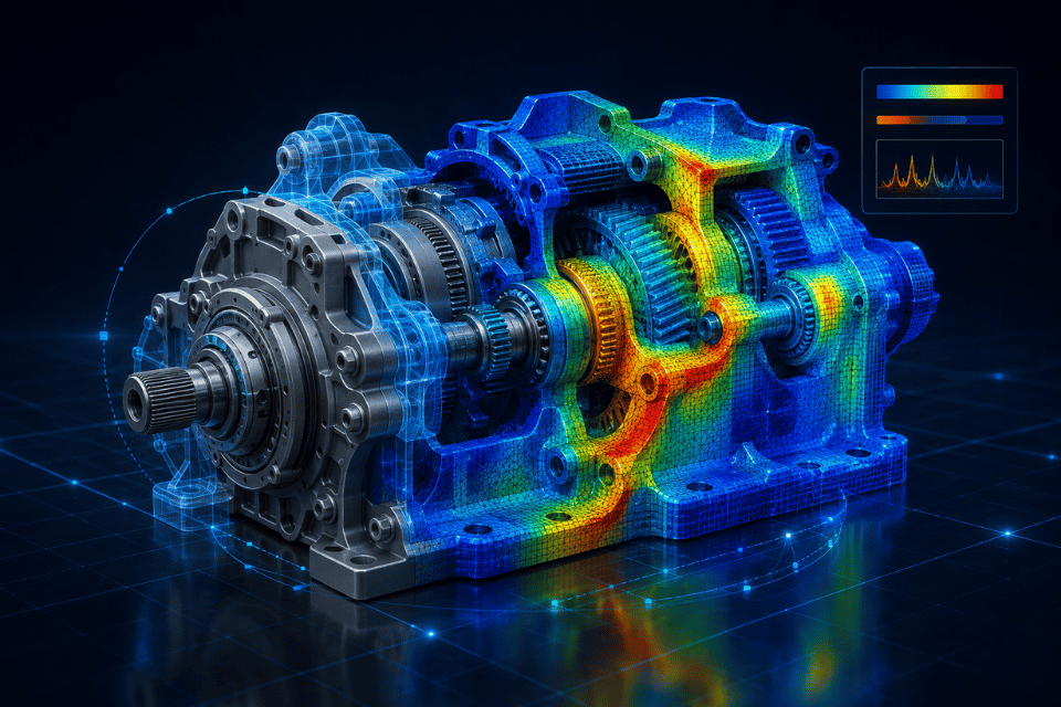
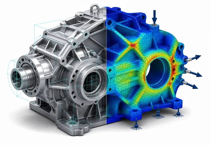
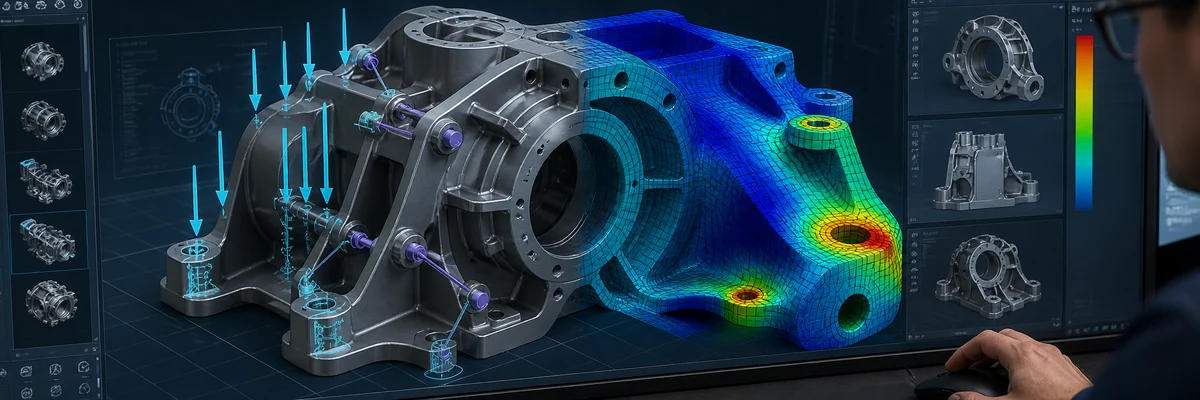
Simulation-Driven Design with Creo Simulation: Perform structural, thermal, vibration, and computational fluid dynamics (CFD) analyses to validate and optimize product performance directly within the native Creo CAD environment.
Request a Commercial Quote →

PTC Creo CAE Licensed Software | Advanced Engineering Simulation Solutions

Simulation-Driven Design with Creo Simulation: Perform structural, thermal, vibration, and computational fluid dynamics (CFD) analyses to validate and optimize product performance directly within the native Creo CAD environment.
Request a Commercial Quote →

Comprehensive Overview​

Creo CAE seamlessly bridges CAD design data with engineering simulation and product validation. Design and CAE engineers can utilize native 3D Creo models, assign material properties, and define boundary conditions and operational loads to validate design concepts long before physical prototyping

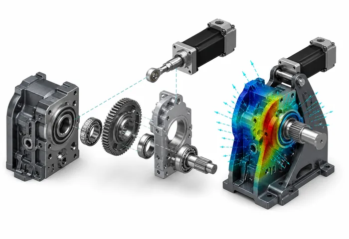
CADCAM Software delivers Creo Simulate—a comprehensive simulation solution for structural, thermal, and dynamic analysis on digital prototypes. It empowers engineering teams to transition smoothly from Creo Parametric into the simulation environment with zero CAD translation loss and no geometry remodeling required.

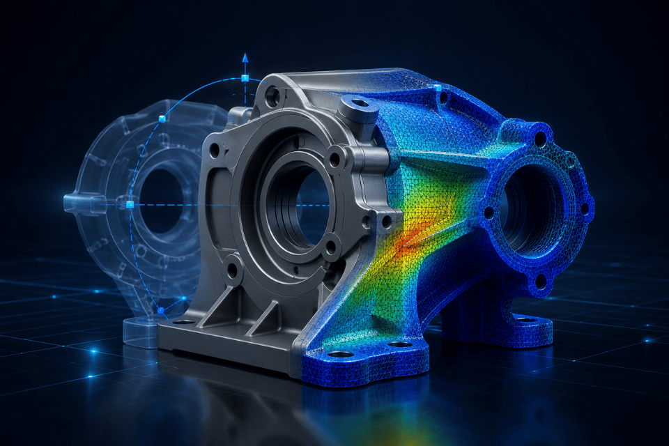
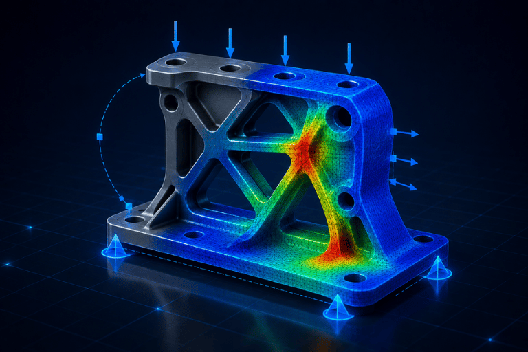
Structural Analysis

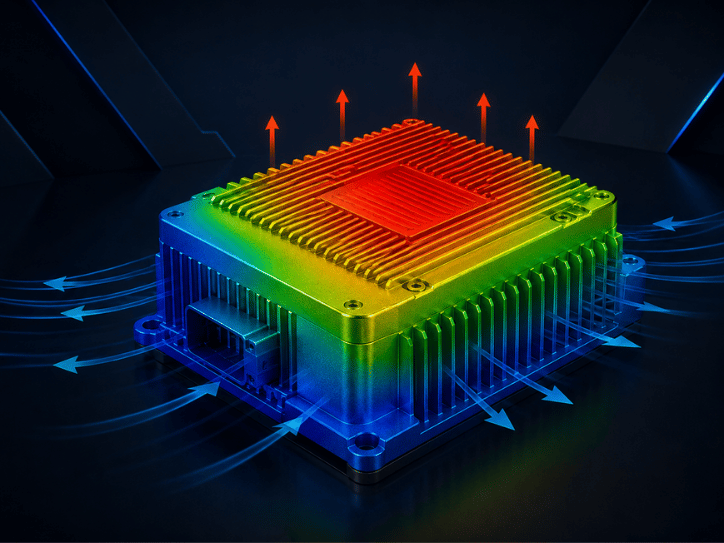
Thermal Analysis

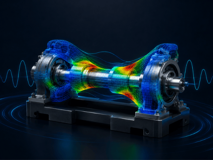
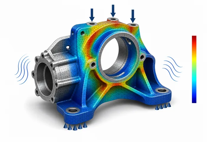
Modal Analysis

Harmonic Response Analysis

Simulation Advancements in Creo 13​

Extended Simulation Capabilities in Creo 13: Creo 13 further expands the simulation-driven design paradigm, empowering engineers to evaluate, iterate, and optimize product designs earlier in the development lifecycle (Shift-Left Strategy).

  • Multiphysics Simulation : Supports multi-scenario evaluations and concurrent multiphysics studies to optimize high-performance mechanical systems.

  • Fast Assembly & Bolted Joint Analysis : Enhanced modeling capabilities for fasteners, bolted connections, contact definitions, and pre-stress loads.

  • Early Real-Time Design Feedback : Real-time simulation feedback enables design engineers to make informed geometry adjustments directly during the active modeling phase.

  • Unified Simulation Suite : Expanded ECAD-MCAD assembly integration in Creo Simulation Live, along with enhanced contact analysis and bolt pre-loads across both Creo Simulation Live and Creo Ansys Simulation.

PTC CREO CAE SIMULATION SOLUTIONS PORTFOLIO

Creo Simulation Live

Real-time, instantaneous simulation feedback embedded in the modeling workflow, allowing designers to evaluate the immediate impact of parametric changes on structural, thermal, and fluid performance.

Creo Ansys Simulation

High-fidelity FEA and multiphysics analysis powered by the industry-leading Ansys solver engine, seamlessly integrated into Creo for structural, thermal, and modal validation.

Creo Simulation Extension

Finite Element Analysis (FEA) extension dedicated to verifying linear structural, steady-state thermal, and vibrational behaviors on digital twins prior to physical manufacturing.

Creo Advanced Simulation Extension

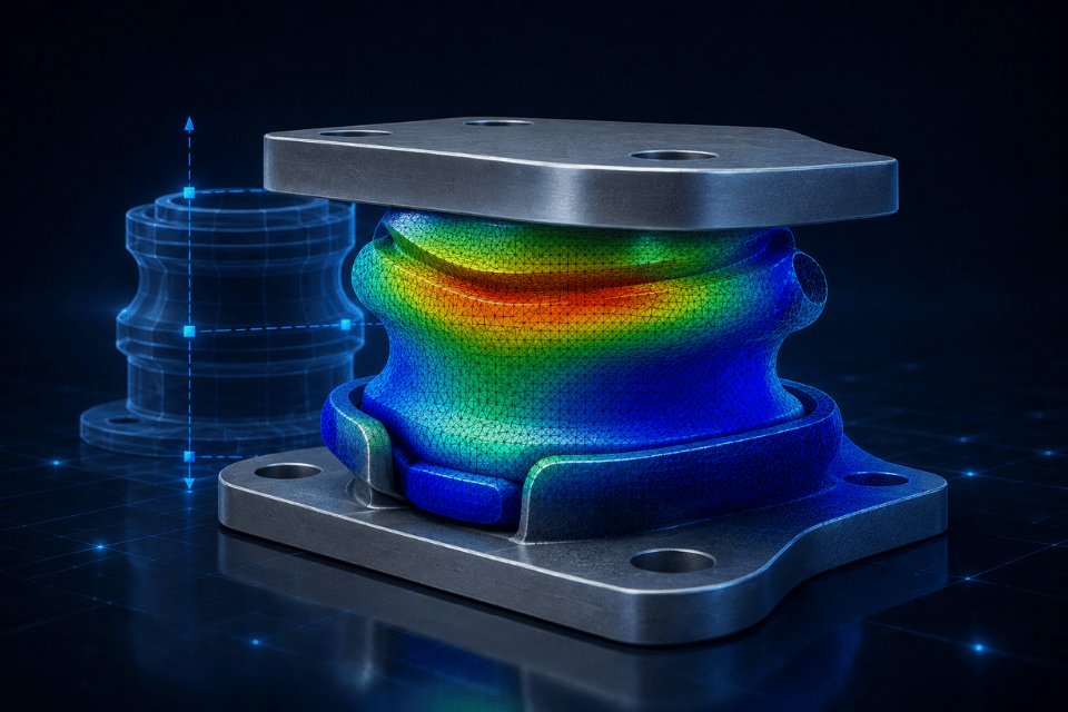
Advanced non-linear FEA solver capable of simulating complex non-linear material behaviors, large deflections, dynamic contact mechanisms, and transient thermal states.

Creo Flow Analysis

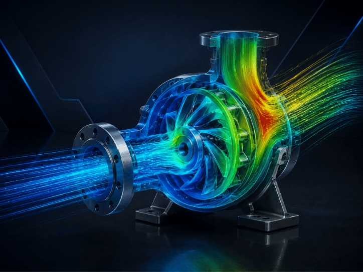
Complete Computational Fluid Dynamics (CFD) solution tailored for internal/external fluid flow simulations, pressure drops, aerodynamics, and conjugate heat transfer (CHT).

Creo Fatigue Advisor Extension

Durability and fatigue life prediction tool that calculates damage accumulation, cyclic load limits, and product operational lifespan under repetitive stress conditions.

Which Simulation Solution Best Fits Your Enterprise

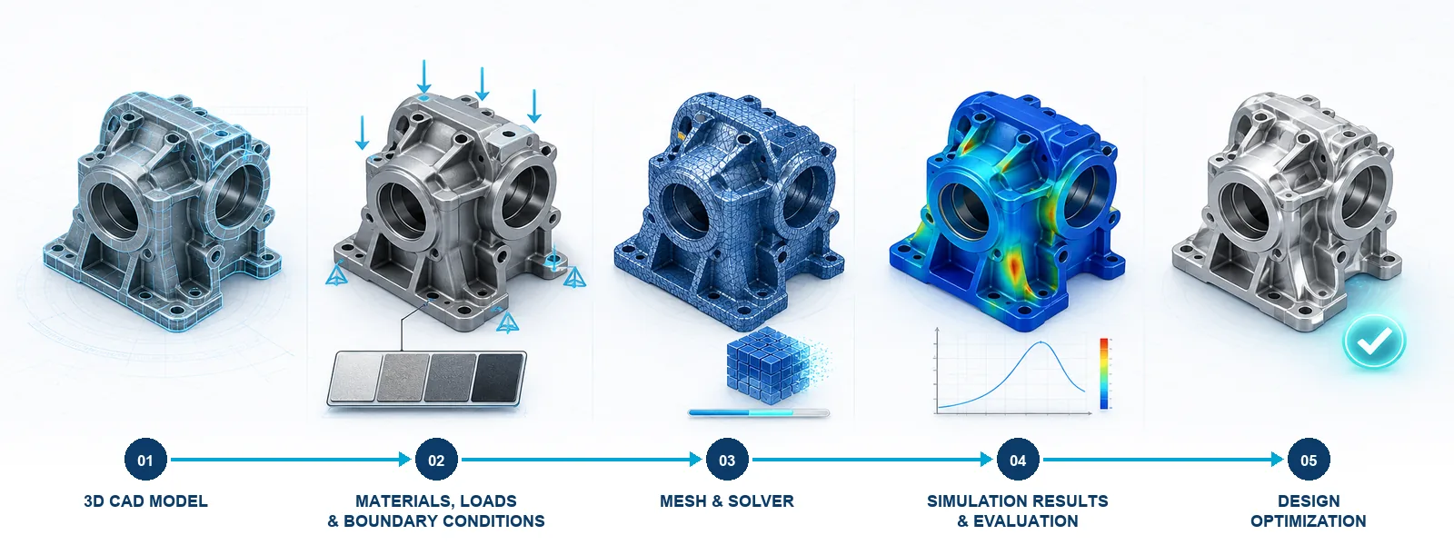
Simulation Workflow

  • Step 1: Model Preparation 

    Directly leverage associative 3D CAD geometry from the Creo Parametric environment.

  • Step 2: Physics & Boundary Setup 

    Assign material libraries, structural constraints, thermal loads, pressures, and operational boundary conditions.

  • Step 3: Solve & Analyze 

    Execute FEA/CFD solvers across structural, thermal, dynamic modal, or fluid flow domains.

  • Step 4: Post-Processing & Result Evaluation 

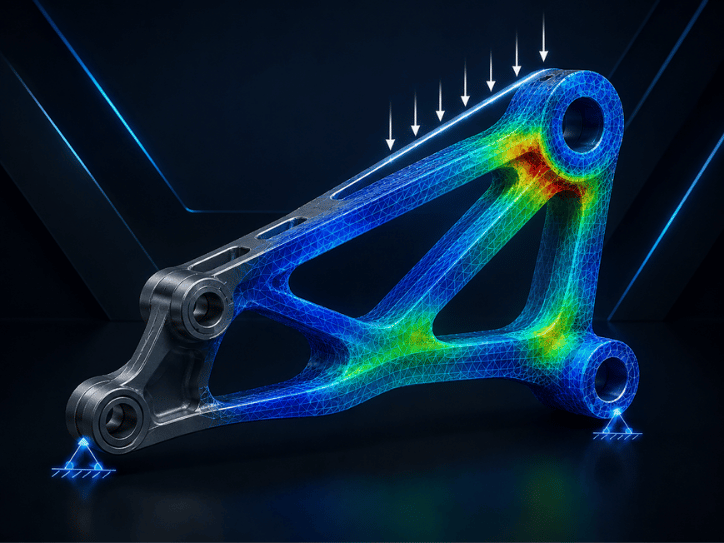
    Visualize stress concentrations (Von Mises), deformation plots, factor of safety (FoS), thermal gradients, and velocity streamlines.

  • Step 5: Design Optimization 

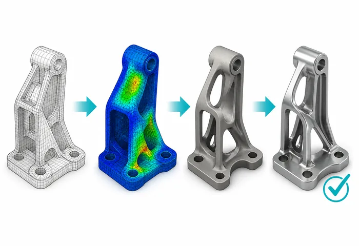
    Parametrically modify CAD geometry and immediately re-validate alternative engineering variants.

Sign Up for Consultation & Licensed Software Quote

FAQ

Depending on the package selected, Creo CAE supports structural analysis (static/dynamic), thermal management (conduction, convection, radiation), modal & vibration response, fatigue durability, and Computational Fluid Dynamics (CFD).

Creo Simulation Live (CSL) provides instantaneous, interactive feedback powered by GPU processing for rapid design exploration during modeling. In contrast, Creo Simulation (FEA) is engineered for high-precision, in-depth numerical validation and formal engineering compliance sign-offs.

Selection depends on your target physical domains, product complexity, compliance standards, and the engineering maturity of your R&D team. Our certified application engineers can perform a technical assessment to recommend the optimal tier.

Việc lựa chọn phụ thuộc vào bài toán vật lý, độ phức tạp của sản phẩm, yêu cầu kết quả và năng lực của người sử dụng